PCB Thickness: Standard Thickness, Factors, Tolerances, and Selection Guide
The thickness of an object is generally defined as the distance between its two outermost surfaces. In mechanical engineering and product development, thickness is an important design parameter because it can affect structural strength, weight, dimensions, and assembly compatibility.
The same principle applies to a Printed Circuit Board (PCB).
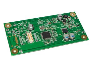
PCB thickness affects mechanical rigidity, connector compatibility, component mounting, fabrication, thermal behavior, electrical performance, and overall product integration. Choosing the right board thickness is therefore an important part of PCB Design and PCB Manufacturing.
So, how thick is a PCB?
The overall PCB thickness is measured from one outer surface of the finished board to the opposite outer surface. Depending on the construction, this overall thickness can include the core materials, dielectric layers, copper foils, solder mask, and surface finish. Silkscreen is normally very thin and contributes little to the nominal board thickness.
Because PCBs are manufactured using laminated structures, the final thickness is determined by the combination of multiple materials and manufacturing processes rather than by a single layer.
This guide explains PCB thickness, common standard values, thickness tolerances, the factors that affect board thickness, and how to select the appropriate thickness for different applications.
What Is PCB Thickness?
PCB Thickness refers to the total thickness of a finished printed circuit board measured between its two outer surfaces.
For a conventional rigid PCB, the construction may include:
- Copper foil
- Core laminate
- Prepreg and other dielectric materials
- Additional copper layers
- Solder mask
- Surface finish
- Silkscreen
In a multilayer PCB, the copper and dielectric materials are stacked and laminated together to form the final board structure.
The nominal thickness specified on a PCB drawing or purchase order generally refers to the finished board thickness, but the exact measurement convention can vary depending on the manufacturer and specification.
For this reason, designers should clearly define the required board thickness and tolerance rather than assuming that a nominal value represents an exact measured dimension.
Why PCB Thickness Matters
Selecting the correct PCB Board Thickness is important because the board must satisfy both electrical and mechanical requirements.
Mechanical Strength and Rigidity
A thicker rigid PCB generally provides greater resistance to bending and mechanical deformation.
This can be important for:
- Large PCBs
- Heavy components
- Large connectors
- Industrial equipment
- Automotive electronics
- Backplanes
- Boards exposed to vibration
However, simply increasing thickness is not always the best solution. Board dimensions, material properties, copper distribution, mounting points, and mechanical support also influence PCB stiffness.
Connector Compatibility
Some PCBs are inserted into:
- Card-edge connectors
- Backplane connectors
- Board-to-board connectors
- Sockets
- Mechanical housings
If the PCB thickness is outside the connector’s specified range, reliable mating may not be possible.
Therefore, connector specifications should be considered before selecting PCB Thickness.
Electrical Performance
Board thickness can influence electrical characteristics, particularly in multilayer and high-speed PCB designs.
The thickness of dielectric layers between copper planes affects:
- Trace impedance
- Capacitance
- Coupling
- Crosstalk
- Return-current paths
- Signal integrity
For controlled-impedance designs, the complete stackup—including dielectric thickness, copper thickness, and material properties—must be considered rather than looking only at the overall board thickness.
Thermal Management
PCB thickness can contribute to thermal performance, but thickness alone does not determine how effectively a PCB dissipates heat.
Thermal performance depends on factors such as:
- Copper thickness
- Copper area
- Thermal vias
- Copper planes
- PCB material
- Component power
- Heat sinks
- Airflow
- Board structure
For high-power designs, increasing copper weight or using dedicated thermal structures may be more effective than simply making the entire PCB thicker.
Manufacturing Reliability
The selected board thickness must be compatible with the manufacturer’s fabrication process.
Very thin or unusually thick boards may require specialized manufacturing capabilities.
Manufacturing considerations can include:
- Lamination
- Drilling
- Plating
- Routing
- Panelization
- Handling
- Warpage control
- Surface finishing
Therefore, the desired thickness should be discussed with the PCB Manufacturer during the design stage when the board has non-standard construction.
Common PCB Thicknesses
There is no single universal PCB thickness for every application.
Common nominal thicknesses for rigid PCBs include:
| Nominal Thickness | Typical Application |
|---|---|
| 0.4 mm | Ultra-thin and compact electronics |
| 0.6 mm | Compact electronic products |
| 0.8 mm | Thin consumer and embedded electronics |
| 1.0 mm | Compact and lightweight designs |
| 1.2 mm | Consumer and industrial electronics |
| 1.6 mm | Common general-purpose rigid PCB thickness |
| 2.0 mm | Industrial and mechanically demanding applications |
| 2.4 mm | Thicker industrial and structural applications |
| 3.2 mm | Heavy-duty and specialized applications |
These are common nominal values rather than mandatory standards.
A PCB manufacturer may offer additional thicknesses depending on the laminate system, layer count, copper weight, manufacturing process, and customer requirements.
The widely used 1.6 mm thickness is particularly common for conventional rigid PCBs, but designers should not select it automatically. The correct value depends on the product’s mechanical, electrical, thermal, and manufacturing requirements.
PCB Thickness Tolerance
A PCB’s nominal thickness is not an infinitely precise value.
Manufacturing processes naturally introduce dimensional variation, so designers must consider PCB Thickness Tolerance.
The acceptable tolerance depends on:
- PCB construction
- Material system
- Layer count
- Copper thickness
- Finished-board specification
- Manufacturing process
- Applicable standards
- Customer requirements
It is therefore not appropriate to assume that every PCB should use a fixed ±10% or ±5% thickness tolerance.
For applications with tight mechanical requirements, the allowable thickness tolerance should be explicitly specified and agreed upon with the manufacturer.
For example, a board designed for a precision connector or a tightly constrained enclosure may require a tighter thickness specification than a general-purpose control board.
Factors That Affect PCB Thickness
Several factors determine the final thickness of a PCB.
1. Number of Layers
Layer count is one of the most important factors.
A two-layer PCB generally requires less laminate material than a multilayer PCB. As the number of copper layers increases, additional dielectric layers and bonding materials are required.
For example, typical nominal constructions may include:
- 2-layer PCB: approximately 0.8–1.6 mm
- 4-layer PCB: approximately 1.0–1.6 mm
- 6-layer PCB: approximately 1.2–2.0 mm
- 8-layer PCB: approximately 1.6–2.4 mm
These ranges are illustrative rather than universal. A multilayer PCB can be engineered to achieve different overall thicknesses depending on the stackup.
2. Core and Prepreg Selection
The core and prepreg materials form the structural foundation of a multilayer PCB.
Their thickness affects:
- Overall board thickness
- Layer-to-layer spacing
- Impedance
- Capacitance
- Mechanical rigidity
- Lamination characteristics
In high-speed designs, dielectric thickness is particularly important because it influences controlled impedance and electromagnetic coupling.
3. Copper Thickness
Copper thickness affects both electrical and thermal performance.
Common copper weights include:
- 0.5 oz
- 1 oz
- 2 oz
- 3 oz
- Heavier copper constructions for specialized applications
As copper thickness increases, the final PCB thickness may also increase depending on the stackup and plating process.
However, copper weight should not be treated as the only factor determining current-carrying capability. Trace width, temperature rise, copper area, ambient conditions, and applicable design requirements must also be considered.
4. Mechanical Enclosure Constraints
The PCB must fit inside the final product.
Mechanical constraints may include:
- Housing height
- Connector position
- Mounting brackets
- Screws and standoffs
- Card slots
- Board-to-board spacing
- Component clearance
For example, a thin consumer device may require a thin PCB, while industrial equipment may provide enough space for a thicker and mechanically stronger board.
5. Board Size
Large PCBs are generally more susceptible to bending and warpage than small boards.
When a large PCB needs to support heavy components or withstand vibration, engineers may consider:
- Increased board thickness
- Additional mounting points
- Structural supports
- Appropriate material selection
- Optimized copper distribution
However, thickness is only one part of mechanical design.
6. Thermal Requirements
High-power electronics require careful thermal management.
Instead of assuming that a thicker PCB automatically provides better heat dissipation, engineers should evaluate the complete thermal structure.
Possible solutions include:
- Heavy copper
- Large copper planes
- Thermal vias
- Metal-core PCB construction
- Thermal interface materials
- External heat sinks
- Improved airflow
The appropriate solution depends on the power density and application.
7. Manufacturing Capabilities
The selected thickness must be achievable using the manufacturer’s available materials and processes.
Very thin and very thick boards can introduce additional manufacturing challenges, including:
- Handling difficulty
- Warpage
- Drilling considerations
- Lamination control
- Plating uniformity
- Routing limitations
- Panelization constraints
For this reason, the desired PCB Board Thickness should be checked against the manufacturer’s capabilities before the design is finalized.
PCB Thickness for Different PCB Types
Different PCB technologies use different thickness ranges.
Rigid PCB
Rigid PCBs are available in many thicknesses, with 1.6 mm being a common nominal value for general-purpose designs.
The actual thickness depends on:
- Layer count
- Material
- Copper weight
- Application
- Mechanical requirements
Flexible PCB
Flexible PCBs are significantly thinner than conventional rigid boards.
Their construction may use:
- Polyimide film
- Copper foil
- Coverlay
- Adhesive layers
- Stiffeners
The final thickness depends on the flexible circuit structure and whether stiffeners are included.
Rigid-Flex PCB
A Rigid-Flex PCB combines rigid and flexible sections within one interconnected structure.
Consequently, the rigid and flexible regions may have different thicknesses.
The transition between these regions must be carefully designed to meet both mechanical and electrical requirements.
Metal-Core PCB
Metal-core PCBs use a metal substrate, often aluminum, to improve thermal management.
Their overall thickness depends on:
- Metal substrate thickness
- Dielectric layer
- Copper layer
- Surface finishes
The metal substrate provides thermal and mechanical benefits but does not mean that the PCB must be universally thicker.
HDI PCB
High-density interconnect PCBs can use very thin dielectric layers and microvias to achieve high routing density.
An HDI PCB can therefore provide high interconnection density without necessarily having an exceptionally large overall board thickness.
How to Choose the Right PCB Thickness
Selecting the correct PCB Thickness requires balancing mechanical, electrical, thermal, and manufacturing requirements.
Consider the Installation Method
Determine how the board will be installed.
Ask:
- Is it mounted with screws?
- Does it slide into a connector?
- Is it installed in a card slot?
- Does it need to fit into a compact enclosure?
- Is it supported by standoffs?
- Will it experience vibration?
These factors can significantly affect the required thickness.
Check Connector Requirements
If the PCB interfaces with an edge connector or socket, use the connector manufacturer’s specified PCB thickness range.
This should be treated as a hard mechanical constraint.
Evaluate Board Size
Large boards may require greater mechanical rigidity or additional structural support.
A larger board with insufficient support may experience bending during assembly or operation.
Consider the Layer Stackup
For multilayer and high-speed PCBs, do not choose total thickness independently of the stackup.
Instead, consider:
- Core thickness
- Prepreg thickness
- Copper thickness
- Dielectric constant
- Reference planes
- Controlled impedance
- Via structures
Consider Manufacturing Cost
Non-standard thicknesses may require special materials or manufacturing processes.
A standard thickness that satisfies the application can often simplify sourcing and manufacturing.
Consult the PCB Manufacturer
Early communication with the manufacturer is particularly important for:
- Very thin PCBs
- Very thick PCBs
- High-layer-count boards
- Heavy copper PCBs
- HDI PCBs
- Rigid-flex PCBs
- High-speed controlled-impedance boards
- Tight mechanical-tolerance applications
This allows the design to be optimized for both performance and manufacturability.
PCB Thickness and PCB Manufacturing
Thickness must remain consistent with the entire PCB Manufacturing process.
During production, manufacturers must control processes such as:
- Material preparation
- Layer alignment
- Lamination
- Drilling
- Copper plating
- Pattern formation
- Solder mask application
- Surface finishing
- Routing
- Final inspection
The finished board may differ slightly from its nominal target because of material and process tolerances.
For demanding applications, thickness should therefore be measured and controlled according to the agreed specification rather than assumed from the nominal stackup alone.
How Kingda Can Support PCB Thickness Requirements
Selecting the appropriate board thickness is easier when the design and manufacturing teams communicate early.
Kingda can support customers with PCB Manufacturing requirements involving different board structures, materials, layer counts, copper weights, and mechanical specifications.
For a new PCB project, engineers can evaluate factors such as:
- Required board thickness
- Thickness tolerance
- Layer count
- Copper weight
- Material selection
- Mechanical dimensions
- Connector compatibility
- Thermal requirements
- Controlled impedance
- Manufacturing feasibility
For non-standard boards, discussing the required stackup and finished thickness with Kingda before production can help reduce design revisions and improve manufacturability.
Frequently Asked Questions About PCB Thickness
What is the standard PCB thickness?
There is no single mandatory PCB thickness for all circuit boards. 1.6 mm is a widely used nominal thickness for conventional rigid PCBs, but many other thicknesses are available depending on the application and manufacturer.
Is 1.6 mm the best PCB thickness?
Not necessarily. 1.6 mm is common and convenient for many applications, but the optimal thickness depends on mechanical strength, connector compatibility, layer stackup, electrical requirements, enclosure constraints, and manufacturing capabilities.
How thick is a 4-layer PCB?
A 4-layer PCB can be manufactured in various thicknesses. Around 1.0–1.6 mm is common for many designs, but the exact thickness depends on the required stackup and manufacturing specification.
How thick is a 6-layer PCB?
A 6-layer PCB may commonly be manufactured around 1.2–2.0 mm, although thinner or thicker constructions are possible depending on the stackup and application.
Does a thicker PCB have better thermal performance?
Not necessarily. Thermal performance depends heavily on copper thickness, copper area, thermal vias, material construction, heat sinks, airflow, and component power density.
Does PCB thickness affect impedance?
Yes. In controlled-impedance designs, the dielectric thickness between a signal trace and its reference plane is an important factor affecting impedance. Total board thickness alone does not determine impedance.
Can PCB thickness be customized?
Yes. PCB manufacturers can offer various nominal thicknesses depending on available materials and manufacturing capabilities. Custom thickness requirements should be discussed with the manufacturer early in the design process.
Conclusion
PCB Thickness is an important parameter in both PCB Design and PCB Manufacturing. It influences mechanical rigidity, connector compatibility, stackup configuration, signal integrity, manufacturability, and product integration.
Although 1.6 mm is a common nominal thickness for conventional rigid PCBs, there is no universal thickness that is suitable for every application. Thin PCBs may be necessary for compact consumer electronics, while thicker constructions may be appropriate for mechanically demanding industrial products. Flexible, rigid-flex, HDI, and metal-core PCBs may use completely different structural approaches.
When selecting board thickness, engineers should consider layer count, core and prepreg selection, copper weight, board size, enclosure constraints, connector requirements, thermal design, electrical performance, manufacturing capabilities, and cost.
The most important principle is to select the PCB Board Thickness based on the complete product requirement rather than choosing a standard value automatically. By defining the nominal thickness and appropriate tolerance early and communicating with an experienced PCB Manufacturer, designers can achieve a better balance between performance, reliability, manufacturability, and cost.