Smart Agriculture Sensor PCB: Design and Manufacturing Guide
Smart agriculture is transforming traditional farming by replacing experience-based decision-making with real-time data, automated control, and intelligent resource management. Sensors deployed in fields, greenhouses, livestock facilities, and aquaculture systems collect critical information such as temperature, humidity, soil moisture, pH, gas concentration, light intensity, and water quality.
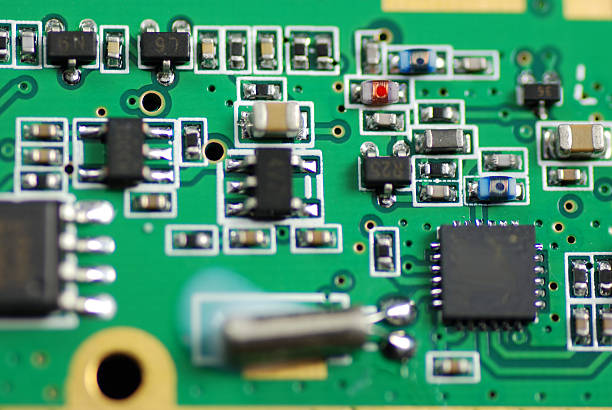
At the center of these sensing devices is the Smart Agriculture Sensor PCB. Although the PCB does not directly interact with soil, crops, water, or livestock, it provides the electrical platform that connects sensors, signal-conditioning circuits, processors, power-management components, and wireless communication modules.
Unlike conventional indoor electronic products, agricultural sensor electronics may operate in environments characterized by moisture, dust, temperature fluctuations, chemical exposure, ultraviolet radiation, and electromagnetic interference. As a result, PCB design and manufacturing must consider environmental protection, signal integrity, low power consumption, wireless connectivity, and long-term reliability.
What Is a Smart Agriculture Sensor PCB?
A Smart Agriculture Sensor PCB is a printed circuit board specifically designed for electronic sensing and monitoring equipment used in agricultural applications.
The PCB can integrate multiple functional circuits, including:
- Sensor interfaces
- Analog signal-conditioning circuits
- Microcontrollers
- Data-processing circuits
- Wireless communication modules
- Power-management circuits
- Battery-management functions
- Memory devices
- Protection circuits
- Communication interfaces
Depending on the application, an agricultural sensor may transmit collected data through technologies such as LoRa, Bluetooth, Wi-Fi, cellular communication, or other low-power wireless networks.
The PCB therefore serves as the connection between physical agricultural conditions and digital monitoring platforms.
Why Agricultural Sensor PCBs Require Specialized Design
Agricultural sensing equipment can be deployed in very different environments. A soil-monitoring sensor buried underground has different requirements from a greenhouse temperature sensor, while a water-quality sensor may operate partially or completely underwater.
This diversity makes application-specific PCB engineering particularly important.
Soil Monitoring Sensors
Soil sensors can measure parameters such as:
- Soil temperature
- Soil moisture
- pH
- Electrical conductivity
- Nutrient-related parameters
Because some sensors are installed close to or inside the soil, the electronics may be exposed to high humidity, moisture, salts, and contaminants.
The PCB should therefore be designed together with the sensor enclosure and sealing system. Depending on the product architecture, conformal coating, protective encapsulation, or other environmental protection methods may be considered.
The objective is to reduce the risk of moisture penetration, corrosion, leakage currents, and electrical instability.
Greenhouse Sensor Systems
Greenhouses often contain multiple sensors monitoring:
- Air temperature
- Relative humidity
- Carbon dioxide
- Light intensity
- Soil conditions
- Ventilation conditions
A greenhouse sensor PCB may need to combine precision analog measurement with wireless communication and low-power operation.
This creates a more complex layout challenge because sensitive analog signals, digital processing circuits, RF modules, and power circuits may occupy the same compact board.
Careful component placement and PCB routing can help reduce interference and improve overall system stability.
Livestock and Poultry Monitoring
Agricultural sensor systems used in livestock facilities may monitor environmental conditions such as temperature, humidity, air quality, and specific gases.
The electronics may be exposed to dust, moisture, cleaning chemicals, and corrosive atmospheric contaminants.
For these applications, the PCB design should consider:
- Protective coatings
- Corrosion-resistant surface finishes
- Sealed enclosures
- Connector protection
- Moisture resistance
- Long-term electrical stability
The appropriate protection strategy depends on the enclosure, installation environment, expected exposure, and required service life.
Aquaculture Sensors
Aquaculture systems can use sensors to monitor water temperature, dissolved oxygen, turbidity, conductivity, and other water-quality parameters.
Electronic assemblies used in these systems need appropriate protection against moisture and water exposure.
The PCB should be designed in combination with the mechanical enclosure, cable connections, connectors, and sealing interfaces. For underwater or high-moisture applications, enclosure-level protection is often just as important as the PCB itself.
Environmental Protection for Agricultural Sensor PCBs
One of the most important differences between an Agricultural Sensor PCB and a typical consumer electronics board is the operating environment.
Moisture and Humidity
High humidity can cause several PCB reliability problems, including:
- Leakage currents
- Surface contamination
- Corrosion
- Insulation degradation
- Electrical instability
PCB designers should therefore consider appropriate solder mask coverage, surface finish, component selection, creepage and clearance, and protective coatings where necessary.
The final protection method should match the environmental conditions and enclosure design.
Temperature Variation
Agricultural equipment may experience significant temperature changes between day and night or across different seasons.
A suitable PCB material should provide adequate thermal stability for the intended operating range.
Material selection should consider:
- Glass transition temperature
- Coefficient of thermal expansion
- Dimensional stability
- Moisture absorption
- Thermal cycling performance
Components should also be selected according to their specified operating temperature range.
Chemical and Corrosion Resistance
Certain agricultural environments can expose electronic assemblies to fertilizers, pesticides, salts, cleaning agents, or corrosive gases.
Corrosion protection can involve several layers of engineering:
- Appropriate PCB material
- Suitable surface finish
- Adequate solder mask coverage
- Protective coating where required
- Proper enclosure design
- Protected connectors and cable interfaces
No single PCB process can eliminate every environmental risk, so the PCB and enclosure should be evaluated as one system.
Signal Integrity and Measurement Accuracy
The primary purpose of a sensor is to obtain accurate information. A PCB that introduces excessive noise or signal distortion can reduce the usefulness of the entire sensing system.
Agricultural sensor electronics may need to process very small analog signals while simultaneously operating wireless communication and digital circuits.
PCB layout should therefore address:
- Short analog signal paths
- Appropriate grounding
- Stable reference voltages
- Power-supply filtering
- Analog and digital circuit separation
- Proper return-current paths
- Decoupling capacitors
- RF circuit isolation
For precision sensing applications, the PCB layout should be treated as part of the measurement system rather than simply a mechanical interconnection structure.
EMI and Noise Control
Agricultural environments can contain significant electrical noise from pumps, motors, irrigation systems, agricultural machinery, power equipment, and long cable runs.
An IoT PCB used for agricultural monitoring should therefore consider electromagnetic compatibility during the design stage.
Potential design approaches include:
- Continuous ground planes
- Proper grounding structures
- Filtering components
- Shielding where appropriate
- Separation of high-noise and low-level circuits
- Optimized signal routing
- Controlled RF layouts
Wireless communication modules require additional attention because antenna performance can be influenced by nearby copper, components, ground structures, cables, and the product enclosure.
Low-Power PCB Design for Smart Agriculture
Many agricultural sensors are installed in locations where replacing batteries frequently is impractical.
Low power consumption is therefore a major design consideration for battery-powered sensor nodes.
A low-power Smart Agriculture Sensor PCB may use several strategies.
Low-Power Components
Microcontrollers and communication modules should be selected according to actual processing and communication requirements.
Modern agricultural sensors can use sleep modes to reduce energy consumption when measurements or wireless transmissions are not required.
Efficient Power Management
The power-management section should be designed according to the battery chemistry, input voltage, sensor requirements, and communication architecture.
Important considerations include:
- Quiescent current
- Conversion efficiency
- Voltage regulation
- Battery discharge characteristics
- Power sequencing
- Transient response
Reducing unnecessary power loss can extend battery life and reduce maintenance requirements.
Optimized Wireless Communication
Wireless transmission can consume considerably more energy than standby operation.
The firmware and hardware architecture can therefore be designed to collect data locally and transmit information at appropriate intervals instead of maintaining continuous communication.
The PCB should provide stable power delivery to the RF module while minimizing interference between wireless and sensing circuits.
PCB Layout for Agricultural Sensor Electronics
PCB layout directly affects electrical performance, thermal behavior, manufacturability, and product size.
A practical layout process should begin with functional partitioning.
Functional Circuit Partitioning
A typical agricultural sensor PCB can be divided into:
- Sensor interface area
- Analog processing area
- Digital processing area
- Power-management area
- Wireless communication area
- Connector area
Keeping these functional regions appropriately organized can simplify signal routing and help reduce unwanted coupling.
Analog and Digital Separation
Sensitive analog circuits should be protected from noisy digital switching circuits.
Designers may use dedicated ground strategies, controlled return paths, filtering, and physical separation to reduce interference.
The exact grounding architecture should be determined based on the circuit topology rather than applying a generic rule to every design.
For projects requiring detailed stackup, routing, and manufacturability optimization, professional PCB Design and Layout can help identify potential design issues before fabrication.
PCB Materials for Smart Agriculture Applications
FR-4 remains a widely used PCB material for many sensor applications because of its combination of electrical performance, mechanical strength, availability, and cost.
However, the appropriate laminate should be selected according to the actual environmental and electrical requirements.
Potential considerations include:
- Operating temperature
- Moisture exposure
- Frequency requirements
- Dimensional stability
- Mechanical requirements
- Required dielectric properties
- Cost targets
For RF-enabled agricultural sensors, material selection may require additional consideration of dielectric characteristics and loss performance.
For demanding environmental applications, the material should also be compatible with the selected protective coating, soldering process, and enclosure system.
PCB Manufacturing Considerations
A reliable PCB Manufacturing process is essential because sensor circuits may contain fine-pitch components, small pads, RF structures, and precision analog circuitry.
Key manufacturing stages include:
- Material preparation
- Inner-layer imaging
- Etching
- Lamination
- Drilling
- Copper plating
- Outer-layer imaging
- Solder mask application
- Surface finishing
- Electrical testing
- Final inspection
Each process can influence the electrical and mechanical performance of the final board.
Copper Plating and Via Reliability
Multilayer agricultural sensor boards rely on plated through-holes and vias to connect different circuit layers.
Consistent plating thickness and reliable hole-wall quality are important for long-term electrical connectivity.
For compact IoT sensor designs, via dimensions and pad structures should also be compatible with the selected manufacturing process.
Surface Finish
The PCB surface finish should provide reliable solderability and appropriate environmental resistance.
Common options may include:
- ENIG
- HASL
- OSP
- Immersion tin
- Other application-specific finishes
The correct choice depends on component packages, assembly requirements, storage conditions, environmental exposure, and cost objectives.
PCB Assembly for Smart Agriculture Sensors
The manufacturing process does not end with bare PCB fabrication. Component assembly also plays an important role in sensor reliability.
A typical PCB Assembly process may include:
- Solder-paste printing
- SPI inspection
- SMT component placement
- Reflow soldering
- AOI inspection
- Through-hole assembly where required
- X-ray inspection for selected packages
- Electrical testing
- Functional testing
For sensor boards, component placement accuracy can be especially important because small passive components and precision ICs may be located close to analog and RF circuits.
The reflow profile should also be optimized according to the PCB materials and component specifications.
Reliability Testing
Because agricultural sensors may remain deployed for extended periods, reliability testing should reflect the expected operating environment.
Depending on the product requirements, testing may include:
Temperature Testing
Thermal cycling can help evaluate the effects of repeated temperature changes on:
- PCB materials
- Solder joints
- Component connections
- Plated holes
- Mechanical interfaces
Humidity Testing
Humidity exposure can help identify potential insulation, corrosion, and leakage-current problems.
Vibration Testing
Agricultural machinery and pumps can generate mechanical vibration.
Sensor assemblies installed on equipment should therefore consider mechanical durability, component attachment, connector reliability, and PCB mounting.
Electrical Testing
Electrical tests can verify:
- Continuity
- Isolation
- Power-rail behavior
- Sensor interfaces
- Communication interfaces
Functional testing can further verify whether the assembled board performs according to the intended system requirements.
Prototype Development and Design Validation
Smart agriculture projects often require multiple development iterations because sensor accuracy, wireless communication, enclosure design, and power consumption are closely interconnected.
A typical development process may include:
- Define sensing requirements
- Select sensors and communication technologies
- Develop the schematic
- Design the PCB stackup
- Complete PCB layout
- Conduct DFM review
- Manufacture prototypes
- Assemble components
- Validate sensor performance
- Test wireless communication
- Evaluate power consumption
- Conduct environmental testing
- Optimize the design
- Release the production version
Using Prototype PCB Assembly during the early development stage allows engineering teams to validate hardware before committing to larger production quantities.
Components and Supply Chain Considerations
Agricultural IoT products often combine sensors, microcontrollers, wireless modules, power-management ICs, connectors, and passive components.
Component availability can therefore have a significant impact on development schedules and production continuity.
When selecting components, engineers should evaluate:
- Availability
- Lifecycle status
- Operating temperature
- Power consumption
- Package type
- Alternative components
- Lead time
- Long-term supply stability
Integrated Components Procurement can help coordinate component sourcing with PCB assembly and production planning.
This approach can reduce the risk of designing a sensor board around components that later become difficult to source.
How Smart Agriculture PCBs Support IoT Applications
The development of smart agriculture depends heavily on the connection between physical sensors and digital platforms.
An agricultural sensor typically follows a data path such as:
Physical Environment → Sensor → Signal Conditioning → MCU → Wireless Module → Cloud Platform → Data Analysis → Agricultural Control
The PCB connects many of these hardware functions.
For example, a soil-monitoring node may measure moisture and temperature, process the sensor signals locally, and transmit the data through a low-power wireless network. The information can then be analyzed by agricultural software and used to support irrigation or other operational decisions.
This makes the IoT PCB an important hardware foundation for connected agricultural systems.
Designing for Manufacturability
A PCB that works in the laboratory is not automatically optimized for mass production.
Design-for-manufacturing should be considered before prototype fabrication.
Important DFM considerations include:
- Minimum trace width and spacing
- Pad dimensions
- Via structures
- Component spacing
- Solder-mask clearance
- Panelization
- Fiducial placement
- Assembly orientation
- Test-point accessibility
Early DFM review can reduce manufacturing problems and help control production costs.
For projects moving from prototype to production, a structured PCB Manufacturing workflow can connect engineering requirements with repeatable fabrication processes.
Future Development of Smart Agriculture Sensor PCBs
Smart agriculture is moving toward increasingly connected and autonomous systems.
Future agricultural sensor designs may require:
- Smaller PCB dimensions
- Lower power consumption
- Higher sensor density
- More integrated wireless communication
- Edge processing
- AI-assisted sensing
- More accurate analog measurement
- Longer battery life
- Improved environmental protection
As more sensors are deployed across farms, greenhouses, livestock facilities, and aquaculture operations, the PCB will need to support greater integration while maintaining low power consumption and reliable operation.
Advanced PCB technologies, compact component packages, flexible interconnects, and improved manufacturing processes can provide additional design options for next-generation agricultural electronics.
Conclusion
The Smart Agriculture Sensor PCB is a critical hardware component connecting agricultural environments with modern digital monitoring and control systems.
From soil moisture and temperature monitoring to greenhouse climate control, livestock environmental monitoring, and aquaculture water-quality management, agricultural sensors must operate reliably under conditions that can be significantly more demanding than conventional indoor electronics.
A successful design needs to consider environmental protection, signal integrity, EMI control, low-power operation, wireless communication, PCB materials, manufacturability, and assembly reliability.
By combining optimized PCB Manufacturing, precision PCB Assembly, appropriate materials, application-specific PCB layout, and comprehensive validation, manufacturers can develop reliable circuit boards for a wide range of smart agriculture applications.
As agriculture continues to become more connected and data-driven, the demand for compact, low-power, environmentally resistant, and highly integrated Agricultural Sensor PCB solutions will continue to grow.