




FCT Testing in PCBA: Functional Circuit Test Guide
FCT testing in PCBA verifies that an assembled circuit board works as designed when power and signals are applied. FCT, which stands for functional circuit test, is one of the last checks before a PCBA is approved for shipment. It confirms that the board can power up, communicate, control outputs, read sensors, and perform the functions expected by the end product. While AOI and X-ray verify that the board was assembled correctly, FCT verifies that the complete circuit behaves correctly.
This guide explains what FCT covers, how fixtures and test programs are developed, and why functional testing is essential for high-quality PCBA delivery.
What Is FCT in PCBA?
FCT is a production test that exercises the assembled board under controlled conditions. The board is placed in a fixture or connected to a test system, power is applied, and a test program checks voltage, current, communication, input-output behavior, and other functional parameters.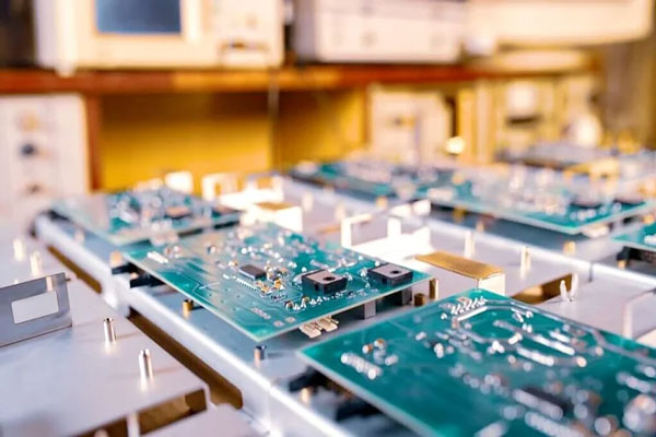
The test is called functional because it evaluates the board’s behavior, not just its physical construction. A board may pass inspection and still fail because of a software issue, damaged IC, wrong component value, or a design problem that only appears when the circuit operates.
FCT is usually performed after solder inspection and electrical tests such as ICT, but it can also be the only electrical check for simpler boards. It can be combined with firmware programming and calibration to create a complete final verification.
Power Testing
One of the first FCT checks is power. The test verifies that each supply rail turns on at the correct voltage and remains stable under the expected load. Current consumption should be within the design range, and there should be no shorts that cause excessive current draw.
Power sequencing matters in boards with multiple supply voltages. If one rail appears before another, some ICs may not initialize correctly. FCT can monitor the startup sequence and confirm that the board follows the intended power state.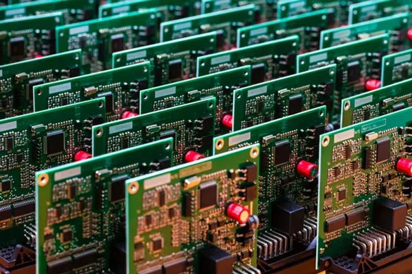
The test should also check power under realistic load so an unstable supply can be detected before the board is installed in the product.
Wireless interfaces need additional checks such as RF power, frequency, sensitivity, and protocol response. These tests may require shielding and calibrated equipment so the measurement is not affected by surrounding interference.
Power tests should also check transient behavior. When a relay turns on or a motor starts, the supply may dip briefly. If the microcontroller resets during that dip, the product will not operate reliably in the real application.
Signal Transmission Testing
Communication is essential in most modern PCBA products. FCT can check UART, SPI, I2C, CAN, Ethernet, USB, wireless modules, and other interfaces by sending data and verifying the expected response.
Signal quality may also be measured for high-speed interfaces. If a board carries high-frequency data, the test should confirm that communication is reliable at the required speed and error rate.
Signal testing is especially important for boards that connect to other devices. A failure in a communication port can be difficult for the customer to diagnose after the product is fully assembled.
Module-Level Functional Checks
FCT can test individual modules on the board. A microcontroller should run its firmware, a sensor should return the correct value, a memory device should store and retrieve data, and a relay or motor driver should respond to control commands.
For boards with displays, buttons, or LEDs, the test can verify user-interface behavior. For power products, it can check protection circuits by simulating overvoltage, overcurrent, or overtemperature conditions.
Module tests are developed from the product specification. The test engineer must understand how each circuit is supposed to work and choose test points that provide access to the needed signals.
The load profile should represent the customer’s actual use case. A board that only sees short operation may need a shorter test, while a continuous-duty product should be checked under sustained load to verify thermal behavior and supply stability.
Load and Stress Testing
Some boards must work under load for long periods. FCT can apply a realistic electrical load and monitor temperature, voltage, and performance over time. This helps identify components that cannot handle their rated current or boards that become unstable when warm.
Load testing is not the same as burn-in, which is usually longer and performed on a sample basis. FCT load tests are designed to be fast enough for every board while still exercising the critical power paths.
The load level should match the actual product operation so the test result is meaningful.
Fixtures must be maintained as production continues. Probes wear out, connectors loosen, and contaminants can build up on contact points. A preventive maintenance schedule for the fixture and test system is necessary to keep results reliable.
Test operators should be trained to recognize fixture errors and record unusual observations. A loose probe or broken test point may produce false failures, and quick diagnosis avoids stopping production unnecessarily.
FCT Fixture and Test Program Design
A good FCT system starts with a fixture that makes reliable contact with the board. Test probes contact pads, connectors, or designed test points. The fixture must support the board without damaging components and provide repeatable alignment.
Test programs should be developed before production and updated through design changes. The program should clearly identify each test step, expected value, and pass-fail limit. It should also save the board serial number, date, operator, and result for traceability.
For high-volume products, test time should be minimized while still covering the critical functions. For complex boards, a longer test may be necessary to verify all modes and interfaces.
Test coverage should also be reviewed whenever the design changes. Adding a new sensor, interface, or power rail without updating FCT can leave the board unchecked for the new function. A controlled change process ensures the test program matches the current product version.
100 Percent Functional Test Coverage
Many quality-focused PCBA suppliers test every board with FCT rather than relying on sampling. This is important because functional defects can occur randomly due to component variation, soldering conditions, or software loading.
100 percent testing gives the customer confidence that each delivered board worked when it left the factory. It also gives the manufacturer immediate data about failures in the production run.
If a board fails, it can be repaired and retested. The failure record should be kept so the engineering team can identify patterns and improve the process.
The same test data can support customer audits and certification reviews. When the supplier can show that every shipped board passed the agreed functional checks, the customer can reduce its own incoming test burden and plan production with more confidence.
FCT and Production Data
FCT results are valuable for manufacturing improvement. The pass rate, failure location, test time, and defect code can be linked to the specific assembly line, operator shift, component lot, or reflow profile.
When the failure rate rises, engineers can analyze the data to find the root cause. This turns FCT from a final gate into an important source of process intelligence.
MES integration allows test data to be combined with material, machine, and process records. This helps the supplier respond quickly to quality issues and provide complete batch documentation.
The benefit is strongest when FCT is combined with upstream controls. If the board is designed with testability in mind and the assembly process is stable, the functional test becomes a fast verification step instead of a repair sorting station.
Benefits of FCT for Customers
Customers benefit from fewer field failures, faster incoming inspection, and better product reliability. A board that has passed functional test can be built directly into the final product without an unexpected surprise.
FCT also reduces the total cost of quality. Finding a failure at the factory costs less than managing a field return, replacing a product, or supporting a customer line stop.
For products that require certification or traceability, FCT records provide evidence that the delivered boards meet the specification.
Choosing a Supplier with FCT Capability
Ask whether the supplier performs FCT on every board, what test coverage is included, and how fixtures are developed and maintained. A supplier that tests only a sample may not provide the same confidence as one that tests 100 percent.
Review how test failures are documented and how the supplier controls changes to the test program. The FCT process should be part of the overall quality system rather than an afterthought.
For integrated service, combine FCT with professional SMT PCB assembly, PCBA testing, and controlled PCB manufacturing so the complete assembly history is traceable. Larger programs can also use turnkey PCB assembly to keep the test process under one quality team.
Conclusion
FCT testing in PCBA is a critical quality step because it proves that the assembled board works as a functional circuit. Power, signal, module, and load checks catch problems that inspection alone cannot see.
With 100 percent coverage, reliable fixtures, clear test programs, and production data analysis, FCT helps manufacturers deliver dependable PCBA products and reduce the risk of field failures.

