




PCBA Quality Control Process: Incoming, In-Process, Final
A strong PCBA quality control process protects the customer from receiving boards with hidden defects and protects the manufacturer from rework, returns, and lost reputation. Quality control in PCB assembly is not one final inspection step. It should begin with incoming material verification, continue through solder paste and placement checks, include automated and X-ray inspection during assembly, and finish with electrical and functional testing before shipment. Each layer of the process catches different problems and creates data that can be used to improve the next batch.
This guide explains the main stages of PCBA quality control, the equipment used at each stage, and the practical benefits of a complete, documented inspection flow.
In practice, the control plan is developed with the customer and tailored to the product’s complexity, volume, reliability requirements, and industry standards.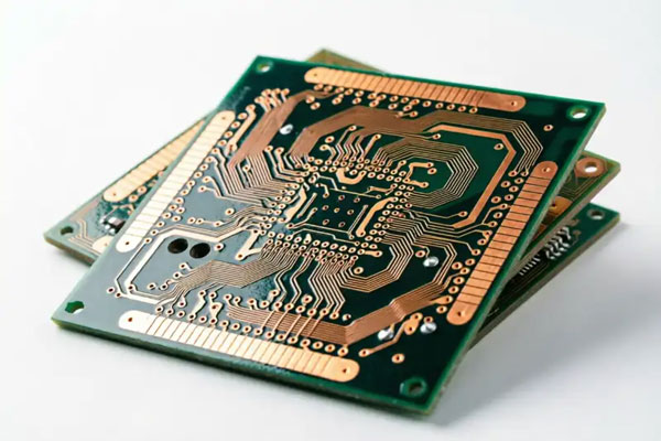
What Is PCBA Quality Control?
PCBA quality control is the set of activities used to confirm that assembled boards meet the design specification and the customer’s quality requirements. It includes inspection, measurement, testing, documentation, and corrective action.
Quality control differs from quality assurance. Assurance focuses on building systems that prevent defects, while control focuses on measuring and checking the product during production. Both are needed in a mature electronics manufacturing environment.
The control plan should identify what to check, when to check it, how many boards to inspect, which acceptance criteria to use, and what action to take when a failure is found.
Component sourcing should be controlled from the beginning. Buying from authorized distributors, maintaining approved supplier lists, and verifying each delivery reduces the chance of receiving a counterfeit or substituted part. An integrated component procurement system makes this process easier to manage.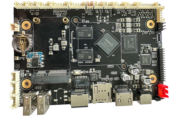
Incoming Material Inspection
The first quality control point is incoming material. Components, PCB bare boards, solder paste, and other materials should be verified before they enter production. A wrong component can cause thousands of boards to fail even when the assembly process is perfect.
Incoming inspection may include checking markings, dimensions, electrical parameters, date codes, quantity, and packaging. Moisture-sensitive devices should be checked against their floor-life requirements. The inspection records should identify the supplier and lot for traceability.
When components are sourced from authorized distributors and verified at incoming, the production line starts with a lower risk of counterfeit or defective material.
Solder Paste Printing and SPI
Solder paste quality is the beginning of assembly quality. If the paste is too thin, too thick, misaligned, or contaminated, the resulting joints can be weak even if placement is correct. Solder paste inspection should be performed after printing and before placement.
A 3D SPI system can measure paste height, area, volume, and position on each pad. It identifies clogged apertures, insufficient paste, solder balls, and smearing while the board can still be cleaned and reprinted without losing expensive components.
SPI data also supports the printer adjustment process. If paste volume begins to drift, the operator can correct the stencil cleaning frequency, print speed, or pressure before the defect rate increases.
SMT Placement Quality
After paste printing, components are placed by high-speed machines. Placement errors such as missing parts, wrong orientation, shifted components, and incorrect value can create defects that are difficult to repair later.
The placement process should be verified with a first article before production and monitored with automated optical inspection after reflow. Feeder setup, nozzle condition, and machine calibration should be controlled.
For fine-pitch components and small passives, precise placement is even more important because the acceptable error is small. A capable SMT PCB assembly process uses equipment and inspection matched to the component types on the board.
AOI programs should also be validated against known-good and known-bad boards before production. This reduces false rejections that waste time and false accepts that let defects pass. The program should balance speed with the sensitivity needed for the specific board design.
AOI after Reflow
Automated optical inspection after reflow checks component presence, position, polarity, solder joint shape, bridges, and other visible defects. AOI compares the board to the expected design using trained programs and can inspect large quantities quickly.
AOI should be programmed for each product variant and updated whenever the design changes. A board with a different capacitor position or component value must have an updated AOI program to avoid false accepts or false rejects.
The inspection result should be recorded by serial number so failures can be traced and analyzed.
The X-ray inspection method should be matched to the board. 2D X-ray is faster and useful for many solder joint checks, while 3D X-ray provides more detail for stacked structures and complex packages. The quality engineer should choose the method that gives enough information without slowing production unnecessarily.
X-Ray Inspection
Some defects are hidden under components. BGAs, QFNs, connectors, and components under shields cannot be fully verified with AOI. X-ray inspection is needed to check solder joints that are not visible from the top or bottom.
X-ray can detect voids, missing balls, bridges, solder thickness, and alignment problems. It is especially valuable for boards that will be used in high-reliability applications such as automotive, medical, and communications equipment.
Sampling or full X-ray coverage should be defined in the quality plan. A defect found only by X-ray can cause intermittent connection failure if it is not caught before shipment.
Soldering parameters such as preheat time, conveyor speed, solder wave height, and temperature should be monitored during the run. A small drift can change joint quality even when the machine appears to be working normally.
Through-Hole Assembly Control
Through-hole components are common on industrial, automotive, and power boards. Wave soldering, selective soldering, or manual soldering should be controlled to prevent bridges, incomplete joints, and thermal damage.
The board design should allow sufficient pad and hole size for the selected soldering process. Fixture design and soldering parameters should be reviewed during process qualification.
After through-hole assembly, the board may require a second AOI pass or visual inspection because the solder joints have different geometry from SMT joints.
Test fixtures and programs should be validated before the first production lot and checked after any design or software change. The test station should also be part of the calibration program so its measurements remain accurate.
Electrical and Functional Testing
Visual and X-ray inspection cannot prove that the circuit works. Electrical testing such as ICT checks opens, shorts, and component values. Functional testing applies power and signals to verify the board’s behavior.
The test plan should cover every critical function of the product. If a board contains firmware, the test may include programming and software verification. If it contains sensors, the test should confirm the sensor output.
Testing 100 percent of boards gives the highest confidence, while sampling may be acceptable for products where the process is very stable. The customer and supplier should agree on the test scope before production.
Quality Control Equipment and Team
Modern quality control depends on advanced equipment such as automatic solder paste printers, multi-zone reflow ovens, SPI, AOI, X-ray, and test systems. However, equipment alone is not enough. Experienced quality engineers must interpret the data and decide how to respond.
The quality team should understand IPC acceptance criteria, component behavior, failure mechanisms, and process limits. Training and certification keep the team capable as technology changes.
Documentation should include inspection reports, test results, repair records, and final quality certificates. This information supports customer audits and helps identify improvement opportunities.
Continuous Improvement
A PCBA quality control process should not be static. Defect data from SPI, AOI, X-ray, and testing should be reviewed regularly to identify the most frequent problems. Corrective action should address the root cause rather than only repairing the affected board.
If soldering defects increase after a new material lot, the quality team should check paste characteristics, stencil performance, and reflow profile. If placement errors appear, the team should verify feeders, nozzles, and machine calibration.
The quality plan should also be updated when the customer changes requirements, introduces a new component, or modifies the product design. Effective improvement reduces cost and increases reliability over time.
The customer should also receive clear documentation describing what quality checks were performed. This can include an inspection summary, test report, X-ray sampling record, and certificate of conformance when required by the contract.
How Customers Benefit
Customers benefit from fewer defective boards, faster incoming inspection, more predictable deliveries, and lower total cost. A supplier with a complete quality control process can provide data that gives the buyer confidence in every lot.
When quality control is linked with PCB manufacturing and a strong quality management system, the customer has one accountable partner for the whole electronic assembly process.
A documented control plan also helps the factory remain consistent when operators or engineers change. Standard procedures reduce the chance that quality depends on one person’s memory.
Conclusion
A PCBA quality control process is most effective when it starts with incoming material and continues through every stage of assembly and test. SPI, AOI, X-ray, ICT, and FCT each provide different information that inspection alone cannot supply.
By combining advanced equipment, trained quality engineers, clear acceptance criteria, and continuous improvement, manufacturers can deliver reliable PCBA products with minimal hidden risk.


