




AOI in PCB Detection: How It Improves Assembly Quality
AOI in PCB detection is used to check the quality of solder paste printing, component placement, and soldering joints during SMT production. AOI stands for automatic optical inspection. The system captures images with CCD cameras, processes them with computer software, and compares the result with a standard image to find defects.
PCB assembly is moving toward high-density and small-size products with mixed technology. AOI helps reduce the number of defective boards that reach the next process step and provides the process data needed for continuous improvement.
This guide explains how AOI works in PCB detection and why it has become one of the most important quality tools on an SMT line.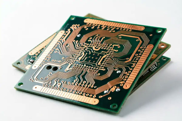
How AOI Works
An AOI system uses one or more CCD cameras to capture an image of the PCB. The image is then processed by an image card and computer software system.
The software compares the captured image with a reference image or with the CAD data for the board. Differences outside the allowable range are identified as defects and saved in an inspection file.
AOIs can inspect the board at high speed, which makes it possible to check every board on the production line rather than only a sample.
The result is a repeatable inspection process that does not depend on the eyesight or attention of one operator.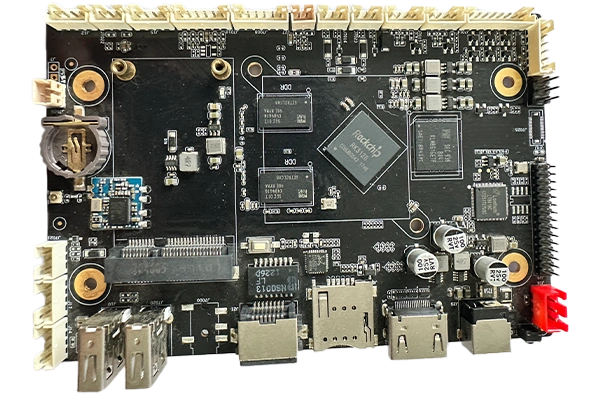
Early Defect Detection
AOIs can find and eliminate errors in the early stage of the assembly process. A printing defect can be detected before components are placed, and a placement defect can be detected before the board enters the reflow oven.
Early detection avoids sending defective products into later assembly stages, where the defect may be covered by another component or process.
If the board is caught early, rework is easier and the component can often be replaced without damage. AOI therefore reduces maintenance cost and prevents scrapping PCBs that cannot be repaired later.
The savings from early inspection are much larger than the cost of the AOI system.
Why PCB Assembly Needs AOI
The manufacturing quality of the PCB directly affects the reliability of the final electronic product. A small solder bridge, missing component, or misplaced resistor can cause the whole product to fail.
Modern boards use fine-pitch components, BGAs, QFNs, and small chip devices. The assembly density is so high that a manual visual check cannot inspect every joint quickly enough.
The need for automatic optical inspection grows as board density increases. AOI provides a fast, accurate method that can keep up with the SMT production line.
AOI technology has scientific advantages that traditional detection methods cannot match, including speed, reliability, and the ability to generate process statistics.
AOI Reduces Process Monitoring Cost
Checking and correcting defects during process monitoring is much less expensive than finding them at final test. A defect found after coating, packaging, or shipment may require the entire assembly to be scrapped.
AOIs placed after solder paste printing can detect paste missing, insufficient paste, bridges, and misalignment before components are placed. This prevents the assembly cost from being added to a board that already has a fatal defect.
AOIs placed after placement can find missing components, reversed polarity, wrong parts, and shifted components before reflow. The defect can be corrected without desoldering.
Post-reflow AOI checks the final solder joints and reports bridges, opens, and poor wetting before the board reaches functional test.
Find Repetitive Errors Early
AOI can detect repetitive errors as soon as they begin. If a placement machine starts to shift every component in one area, the AOI result will show the same deviation on every board.
A misplaced component can be caused by a feeder that is out of position, a worn nozzle, or a board fiducial problem. AOI data points the operator to the exact component and defect type.
Pallet or tray setup errors can also be found in the first few boards instead of after a full lot has been produced. Correcting a repetitive error early prevents large quantities of scrap.
This makes AOI a process control tool, not only a final inspection tool.
AOI Data and SPC
AOI software has statistical analysis functions that can be connected with SPC process management. The system records the location, type, and frequency of each defect.
SPC charts show whether the process is stable or whether a defect rate is increasing. The data helps the engineer identify the root cause before the problem creates a large scrap cost.
For example, an increasing number of bridges on one board area may indicate a stencil problem, while missing components may indicate a feeder or vacuum problem. The statistics point directly to the source.
The combination of AOI and SPC significantly improves the yield of PCB assembly and gives the factory a powerful tool for timely process improvement.
AOI Meets High-Density Test Requirements
Traditional testing technologies such as ICT require physical test points and special fixtures. As assembly density increases, it becomes harder to place test probes on every net.
AOI does not require test points. It inspects the actual image of the board, so the component density does not reduce the coverage of the inspection.
AOIs can inspect very fine features that are difficult or impossible to check with a bed-of-nails tester. This makes it a valuable tool for dense BGA and QFN designs.
AOI should not completely replace electrical testing, but it can cover the visual defects that electrical test cannot detect.
Program Generation From CAD Data
The test program for an AOI system can be generated directly from the CAD data of the PCB. Component positions, pad shapes, and reference images are loaded into the AOI program.
This reduces the time needed to create an inspection program for a new product. The program can also be checked against the actual board during first article production.
Because AOI does not require a special fixture, the test cost is much lower than ICT for many products. A program change is also easier when the board design is revised.
CAD-based programming helps the factory start new products faster and maintain consistent inspection quality.
AOI Keeps Up With the Production Line
AOI systems are designed to run at line speed. Some systems can inspect a frame in about 0.1 seconds, allowing every board to be checked without becoming a bottleneck.
The inspection speed depends on the board size, the number of inspection areas, and the required resolution. The AOI program should be optimized so that line speed is not reduced unnecessarily.
If the AOI becomes too slow, it can be used offline or the inspection area can be reduced to critical components. The goal is to provide complete coverage at the speed required by production.
Fast inspection makes it possible to stop the line quickly when a process begins to drift.
AOI Reliability Compared With Manual Inspection
Manual visual inspection has natural limitations. An operator can become tired, distracted, or inconsistent between boards. Small fine-pitch defects may be invisible under normal lighting.
AOI uses the same camera settings and program for every board, so its accuracy remains constant during the shift. It can also measure dimensions more precisely than the human eye.
AOI is not affected by the fatigue or mood of the inspector. This gives the factory better accuracy and reliability for high-volume production.
Human review is still important for the borderline results reported by AOI, but the machine handles the repetitive task of comparing every board.
AOI Limitations
AOIs can only detect defects that create a visible difference in the image. Solder joints hidden under a BGA body must be inspected by X-ray, not by an optical camera.
AOI cannot measure component values or verify that a chip contains the correct program. Electrical testing is still needed to confirm circuit function.
AOI programs must be set correctly to avoid excessive false calls. A program with very tight limits will report many acceptable boards as defective, slowing the line and increasing review work.
The system should be calibrated regularly so that lighting, camera focus, and board position remain accurate.
Combining AOI With Other Inspection Methods
A complete quality plan uses AOI at the process steps where visible defects occur, X-ray for hidden joints, and ICT or functional test for electrical behavior. The inspection methods complement each other.
A professional PCBA testing service should define which method is used for each product and process step. The factory should review the test coverage with the customer before production.
AOI data should be included in the quality management system. Defect rates, repair actions, and process changes should be traceable to the production lot.
For high-volume production, the factory should use AOI during SMT PCB assembly so that defects are corrected while the process is still running.
An experienced PCB assembly partner can use AOI and SPC data to reduce scrap, improve yield, and deliver consistent boards.
Conclusion
AOI in PCB detection provides fast, accurate, and repeatable inspection of solder paste, placement, and soldering quality. It detects defects early, reduces rework, and supports SPC process control.
AOI can keep up with high-density SMT lines and inspect boards without the fixtures required by ICT. Its program can be created from CAD data, which reduces setup cost and time.
When combined with X-ray and electrical testing, AOI helps manufacturers deliver reliable PCBA products and continuously improve their production process.


