




PCB Reflow Warpage Prevention: Bending Control Guide
PCB reflow warpage prevention is necessary because the board must remain flat while it is heated, soldered, and cooled inside the reflow oven. During SMT assembly, the PCB can bend or warp when it is exposed to the high temperature of reflow soldering. Board deformation can shift components, create opens, and cause solder defects.
The amount of warpage depends on the board thickness, material, size, copper distribution, and the thermal profile. The assembly engineer and PCB designer should consider all of these factors before the board is released for production.
This guide explains the main causes of reflow board bending and the countermeasures used to keep the PCB flat.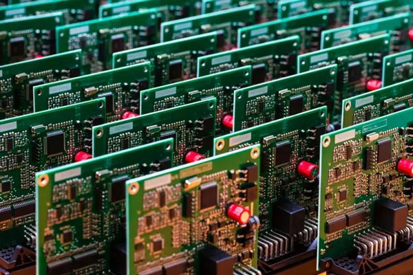
Why PCBs Bend During Reflow
After components are placed on the mounter, the PCBA board must pass through the reflow oven. During the heating process, the board material expands and the resin softens. If the board is not supported or the temperature is not controlled, it can warp.
The temperature difference between the top and bottom surfaces also creates stress. If one side of the board is heated faster than the other, the material expands unevenly and the board bends.
Board thickness, copper distribution, and component mass affect how the board responds to the heat. A thin board with uneven copper is more likely to warp than a thick, balanced board.
Reduce the Influence of Temperature
Temperature is the main source of PCB stress during reflow. Reducing the peak temperature or slowing the heating and cooling speed can greatly reduce board bending and warping.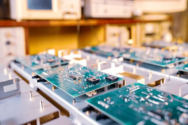
The reflow profile should be selected for the board material and the solder alloy. A slower preheat gives the board time to reach a uniform temperature before the solder melts.
Cooling should also be controlled so that the board does not receive a thermal shock. A very fast cooling rate can increase the residual stress inside the board.
However, reducing the temperature too much may create solder shorts because the solder does not reach its full liquidus temperature for enough time. The profile must balance warpage control with soldering quality.
Use High-Tg Board Material
Tg is the glass transition temperature. It is the temperature at which the board material changes from a glass state to a rubber state.
A material with a low Tg softens soon after it enters the reflow oven and remains soft for a longer time. During that period, the board has less resistance to deformation.
High-Tg materials can improve the ability of the circuit board to withstand stress and deformation at the reflow temperature. However, high-Tg boards are more expensive than standard materials.
The material should be selected according to the product reliability requirement, not only the cost. High-Tg material is often worth the extra price for automotive, industrial, and high-temperature products.
Increase Board Thickness When Possible
Many modern electronic products are designed to be light and thin. Circuit boards with a thickness of 1.0, 0.8, or even 0.6 millimeters are common in portable devices.
A thin board has less rigidity and is more likely to deform after reflow soldering. It is difficult to keep a very thin PCB completely flat through the complete thermal cycle.
If the product does not require a thin board, a thickness of about 1.6 millimeters is recommended. The thicker board greatly reduces the risk of bending and warping.
The required board thickness should be confirmed with the mechanical design before the PCB stackup is finalized.
Reduce Board Size and Panel Count
Most reflow ovens use a chain or conveyor to drive the circuit board forward. A larger board sags more under its own weight at the reflow temperature.
The long side of the circuit board should be placed along the conveyor direction so that the board is supported by the chain along its strongest dimension. This can reduce sag and deformation caused by the weight of the board.
Reducing the number of circuits in a panel also reduces the total size and weight of the panel. A smaller panel reaches the minimum sag deformation more easily.
The panel size should be planned with the oven width and the board flatness requirement in mind.
Balance Copper on Both Sides
Copper distribution affects the thermal expansion of the board. If one side has much more copper than the other, the two sides expand differently and create warpage.
The designer should balance the copper area on the top and bottom layers as much as possible. Large solid copper planes should be distributed so that the board remains symmetrical.
Copper pours should also be separated into smaller areas so that the local expansion does not create a large bending force.
Copper balance is especially important for thin boards and large panels.
Use a Furnace Tray or Pallet
If the board cannot be redesigned, the last method is to use a furnace tray. The tray supports the PCB during reflow and reduces bending and warping.
The tray should hold the circuit board securely during thermal expansion and contraction. When the board cools below the Tg value and hardens again, it can return to its original size.
If a single-layer tray is not enough, another cover can be added. The upper and lower trays clamp the circuit board so that it cannot deform during reflow.
However, reflow trays are expensive and require manual placement and recovery. The tray design should provide openings for the solder joints and allow the board to be heated evenly.
Design the Stackup for Flatness
The PCB stackup should be symmetric in layer count, copper weight, and prepreg arrangement. A symmetric stackup reduces the internal stress created when the laminate is pressed and heated.
The resin system and glass fabric should be selected for the expected reflow temperature. Low-flow or high-Tg prepreg may be used for boards that need better flatness.
The bare board manufacturer should control the lamination pressure, temperature, and cooling rate so that the board leaves the press flat.
Incoming boards should be measured for warp and twist before assembly. A board that is already warped cannot be corrected by the assembly process.
Control Panel Routing and Breakaway Tabs
Panel routing and breakaway tabs also affect board flatness. A panel with long unsupported areas can bend before it enters the reflow oven.
The routing pattern should provide enough support for each circuit. Perforations and V-grooves should be placed so they do not weaken the panel in the conveyor direction.
Depaneling should be performed after reflow and cooling, using a method that does not bend the individual boards.
Measure Warpage in Production
The assembly factory should measure the board flatness during first article production. A warpage gauge or a flat surface check can show whether the board meets the acceptable limit.
Warpage is often measured as a percentage of the board diagonal. The allowable limit depends on the board size, component types, and assembly process.
If the board warps after reflow, the factory should check the profile, support method, and material. A repeatable measurement makes the correction visible.
The measurement should be repeated after process changes so that the improvement can be confirmed.
A professional PCB manufacturing partner should supply flat, high-quality boards with a suitable Tg and balanced stackup for the SMT process.
The board design should be reviewed by the PCB design and layout team to balance copper and plan the panel size.
During SMT PCB assembly, the process engineer should select a profile that avoids excessive warpage while producing complete solder joints.
After soldering, PCBA testing and inspection confirm that the board remained flat enough for correct component alignment and function.
All material and process data should be documented in the quality management system so repeat production uses the same flat board design.
Thermal Profile and Warpage Relationship
The reflow profile should be developed for each board size and thickness. A profile that works for a 1.6 millimeter board may be too aggressive for a 0.8 millimeter board. The engineer should measure the actual board temperature and the warpage together during the profile run.
A slower preheat reduces the temperature difference between the top and bottom of the board. It also gives moisture and solvent time to escape before the solder melts. The soak stage helps the board reach a uniform temperature before the peak zone.
Cooling should be controlled so that the board does not become locked into a bent shape. A balanced cooling rate reduces the internal stress left in the laminate after soldering.
Incoming Board Flatness Control
The PCB supplier should measure warp and twist before shipment. The inspection should follow the IPC flatness limit or the customer specification. A board that fails the flatness test should not be sent to the assembly line.
The assembly factory should also measure the boards when they arrive. Storage should be flat and dry so that the boards do not absorb moisture or develop a permanent set. Boards should not be stacked with heavy components on top of them.
If a new PCB lot arrives with a different warp value, the process should be reviewed before the lot is produced. The incoming check protects both the assembly yield and the final product reliability.
Conclusion
PCB reflow warpage prevention starts with board material, thickness, size, and copper balance. The reflow profile and conveyor support must also be controlled.
High-Tg material, a thicker board, smaller panels, and furnace trays can reduce bending when the design requires a thin or large PCB.
With careful design and process control, the PCBA can pass through reflow while remaining flat and reliable.


