




RF Switch Module PCB Design: VXI and Layout Guide
RF switch module PCB design must combine high-frequency circuit layout with reliable digital control. Modern wireless communication, mobile communication, radar, and satellite systems require switches with high speed, high power capacity, and high integration. A well-designed module can be controlled by a computer and integrated into an automated test system.
An RF switch module can be built on a modular instrument bus so that the computer controls which RF path is connected. The module contains a bus interface circuit and an RF switch function circuit that must be isolated from each other to reduce interference.
This guide explains the main design blocks and PCB layout rules for an RF switch module.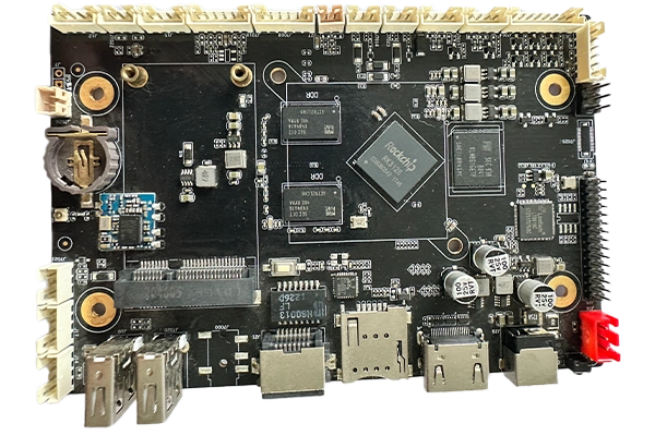
Role of the RF Switch Module
An RF switch routes high-frequency signals between different paths. It may select an antenna, a filter, a test port, or another circuit block according to the control command.
The switch must maintain low insertion loss, good isolation, and a fast switching time. The RF performance depends on both the switch component and the PCB layout around it.
In a test system, the switch can be controlled directly by a computer. This makes it possible to automate signal routing and reduce manual connection errors.
The module should be compact, standardized, and compatible with the test system backplane.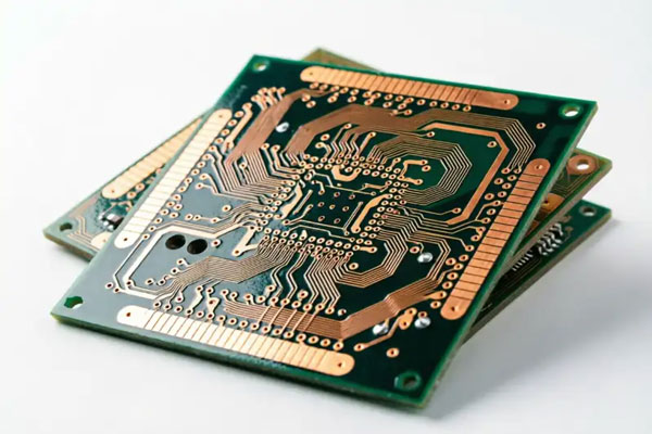
VXI Bus Module Architecture
The VXI bus is an extension of the VME bus used in instrumentation. It is a modular automatic instrumentation system controlled by a computer.
VXI uses an open architecture and plug-and-play design, which allows instruments from different manufacturers to work together. The bus provides high-speed data transfer, compact structure, flexible configuration, and good electromagnetic compatibility.
VXI bus devices can be register-based, message-based, or memory-based. Register-based devices are widely used because they are simpler and faster to control.
An RF switch module is often implemented as a register-based VXI device controlled by writing to its control registers.
Bus Interface Circuit
The VXI interface circuit connects the module to the backplane. It must receive address and control information, transfer data, and return the proper handshake signal.
The interface normally includes bus buffering, addressing and decoding, a data transfer state machine, and configuration registers.
Bus buffers isolate the backplane from the module circuits and drive the data lines when the module is selected. Without correct buffering, the module can load the bus and create timing errors.
The interface logic should be designed to meet the VXI signal timing requirements.
Addressing and Decoding
The addressing circuit decodes the address lines and address modification lines from the backplane. It compares the received address with the logical address set by the hardware address switch on the module.
When the address matches, the module is addressed and the decode signal becomes active. The lower decoding circuit then selects the correct register in the module address space.
The address space should be small enough to simplify the design but large enough to include all required registers.
Correct decoding prevents two modules from responding to the same address.
Data Transfer Response State Machine
The data transfer bus is a high-speed asynchronous parallel bus used for information exchange in the system. It is controlled by address lines, data lines, and control lines.
The state machine controls the timing of the data transfer cycle. When the system addresses the module, it sets the address strobe, data strobe, and read or write direction signals.
The module then returns a bus response signal to confirm that data has been placed on the bus for a read cycle or has been received successfully for a write cycle.
The state machine must be designed carefully because the response timing is complex.
Configuration Registers
Every VXI bus device has a set of configuration registers. The system controller reads these registers to learn the device type, model, manufacturer, address space, and memory requirement.
The basic configuration registers include the identification register, device type register, status register, and control register.
The identification, device type, and status registers are usually read-only, while the control register can be written by the system.
For an RF switch module, data written to the channel register controls the on or off state of the relay switches. Reading the same register returns the current relay status.
Separate Control and RF Circuits
The RF switch module contains a bus interface circuit and an RF switch function circuit. The two circuits should be separated to reduce interference.
In some designs, a cable connects the bus interface board and the RF function board. The cable allows the digital and RF sections to be placed in separate shielded areas.
RF signals can couple into digital control lines and disturb the state of the switch. The layout must prevent RF energy from entering the control circuit.
Shielding, ground planes, and filtering should be used at the boundary between the two sections.
RF PCB Characteristics
The frequency range of an RF circuit can extend from about 10 kilohertz to very high frequencies. As the frequency increases, the circuit behaves differently from a DC or low-frequency circuit.
Trace length, impedance, parasitic capacitance, and ground return path all become important. The RF signal should be routed as a controlled impedance transmission line.
The board material should have stable dielectric properties and low loss at the operating frequency.
Every via, bend, and pad in the RF path adds some discontinuity that can affect the signal.
Electromagnetic Compatibility
EMC is the ability of an electronic system to function normally in a specified electromagnetic environment. The system should not radiate excessive energy and should resist interference from other circuits.
For RF PCB design, each circuit module should be arranged so that it does not create unnecessary radiation. The layout also needs to give every module some immunity to external signals.
Good grounding is the first EMC requirement. A continuous ground plane below the RF traces provides a short return path and reduces loop area.
Component placement should also separate high-level and low-level RF signals.
Component Layout Principles
Components should be arranged along the same direction as much as possible. Consistent orientation reduces soldering defects when the board passes through the reflow process.
The spacing between components should be at least about 0.5 millimeters to support soldering. If the board area allows, the spacing should be wider.
Reasonable component layout is also a prerequisite for reasonable wiring. Components that must be connected should be placed so that the trace can be short and direct.
The designer should think about the layout and the routing plan at the same time.
Relay Placement in an RF Switch
When a relay is used to switch the RF signal, it should be placed as close as possible to the signal input and output connectors. This shortens the RF signal line between the connector and the switch contacts.
A short RF path reduces insertion loss and lowers the chance of coupling to another trace. It also makes the next routing step easier.
The control wiring to the relay should not run parallel to the RF trace over a long distance. If the lines must cross, they should cross at right angles or on different layers with a ground plane between them.
RF relays and other switching devices should be verified at the operating frequency during the prototype phase.
An RF switch module should be manufactured with controlled PCB manufacturing processes so that impedance and material properties match the design.
The design should be reviewed with the PCB design and layout team before fabrication.
After assembly, the module should be tested by PCBA testing to verify the digital control and RF switching functions.
A qualified PCB assembly service should handle the high-frequency components carefully and maintain process control through quality management.
Prototype Verification
The first RF switch module prototype should be measured for insertion loss, return loss, isolation, and switching time. The measurement should be performed at the intended operating frequency with calibrated test equipment. A network analyzer can show whether the RF trace, connector, and relay match the design target.
The digital control side should be tested at the same time. The module should be addressed on the bus, the channel register should be written, and the relay state should change. The control software should read the status register to confirm that the module is responding.
Any deviation between the simulated result and the measured result should be reviewed. The most common cause is an incorrect trace impedance, a long stub, or excessive parasitic capacitance at the relay pad.
Production and Test Process
After the prototype passes, the module can be prepared for production. The assembly documentation should include the relay orientation, RF trace inspection points, and special handling notes for high-frequency components.
The factory should inspect the RF connector solder joints and relay pads after assembly. X-ray inspection may be needed for hidden joints, while functional test verifies that every RF path can be switched and measured.
Each production module should be labeled with its revision and serial number. The test data should be stored so that a module returned from the field can be compared with its original measurement.
Conclusion
RF switch module PCB design requires careful planning of the bus interface, control registers, and high-frequency layout. The digital and RF sections should be separated to prevent interference.
Component orientation, spacing, relay placement, grounding, and shielding determine the EMC and RF performance of the module.
With controlled layout and manufacturing, an RF switch module can provide reliable signal routing in modern test and communication systems.


