




SMT Solenoid Valve and PNP Camera Maintenance Guide
SMT solenoid valve maintenance and PNP camera calibration keep a placement machine accurate and reliable. The solenoid valve controls the compressed air used by cylinders, vacuum nozzles, and other moving parts. The PNP camera system positions components and reads fiducial marks. Regular maintenance of both systems prevents sudden machine failure and placement error.
In electronic surface mount production, regular maintenance of instruments and components is necessary to improve efficiency and save cost. A small air leak or a dirty camera lens can reduce the quality of the complete assembly line.
This guide explains the maintenance steps for SMT solenoid valves and the adjustment procedure for the placement machine cameras.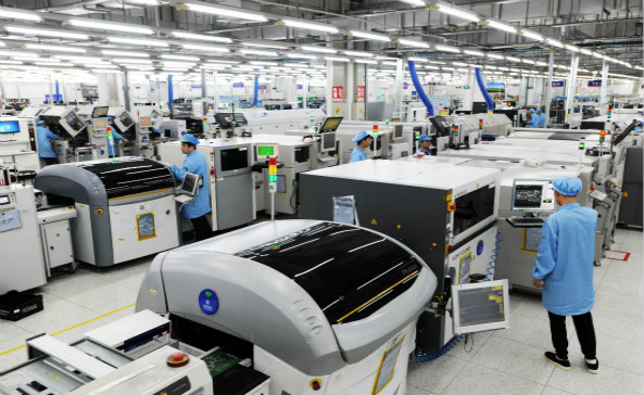
Why Solenoid Valves Need Maintenance
The solenoid valve switches the compressed air supply to different parts of the machine. If the valve sticks, the air cylinder cannot move and the machine stops or places a component incorrectly.
Solenoid valves can collect condensed water, dirt, and worn seals. These contaminants affect the switching speed and the airflow. Maintenance removes the contaminants before they cause a failure.
The maintenance plan should follow the machine manual and the working hours of the valve. Monthly checks are often required for high-speed placement lines.
Confirm Machine Safety First
Before any manual maintenance, confirm that the placement machine is safe to work on. The machine should be stopped and locked out so that it cannot start unexpectedly.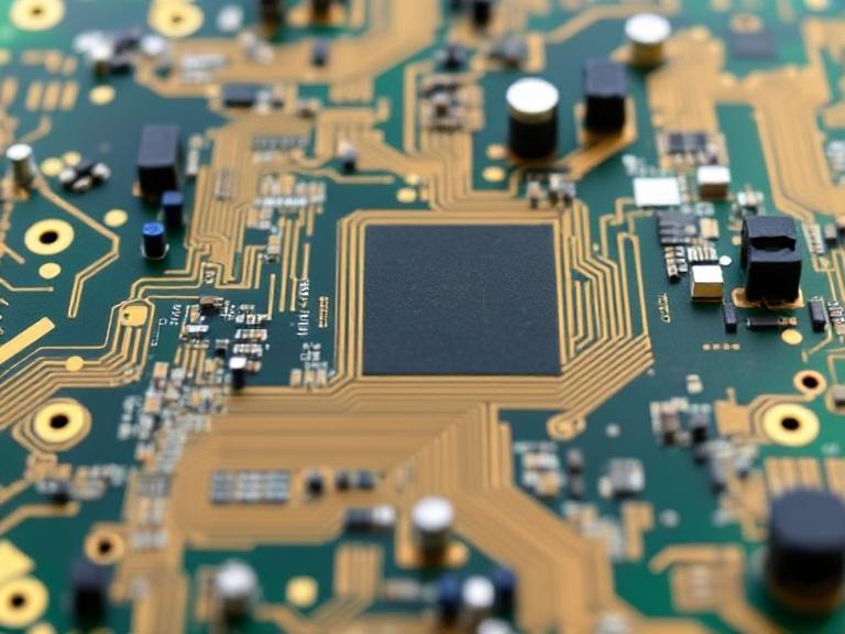
When the machine is disassembled, the equipment must be supported so that a driven object cannot fall or move while the valve is removed.
After the machine is secured, cut off the air supply and the power supply. Pay attention to residual air pressure in the air lines and cylinders before removing a valve.
Residual pressure can make a cylinder move suddenly and cause injury.
Drain Condensed Water
Compressed air contains water vapor that condenses inside the air system. The condensed water should be drained regularly from the air treatment unit.
Water in the air line can damage the solenoid valve, reduce the vacuum, and cause corrosion in the cylinder. The water separator and filter should be checked as part of the daily or weekly routine.
If the factory air compressor does not have a dryer, more frequent drainage is needed.
The air pressure should also be checked after draining so the machine is not started with low pressure.
Test Solenoid Valve Operation
The solenoid valve should be checked at regular intervals to reduce the chance of unexpected failure. A common schedule is to check the valve switching operation once a month.
The test should confirm that the valve opens and closes when the controller sends the command. The operator can listen for the click and watch the cylinder movement.
If the valve makes an abnormal sound, leaks air, or does not switch, it should be cleaned or replaced.
The replacement part should match the original valve type and flow rating.
Follow the Manual Order
The maintenance steps of the placement machine should be carried out in the order given in the operation manual as much as possible. This order protects the operator and prevents damage to the machine.
Disconnect the air and power before removing a valve. Loosen the fittings carefully and do not use excessive force on the valve body.
After the new valve is installed, restore the air and power, then test the valve at low speed before normal production.
The maintenance action and the replacement part serial number should be recorded in the machine history.
PNP Machine Motion System
The placement machine is a fully automatic production machine used in the surface mount industry. Its motion system controls the X, Y, and Z axes and affects the accuracy and speed of the assembly machine.
The drive system transports the PCB through the machine. Belt-driven systems move the board from the input position to the placement position and then to the next process.
Sectional driving divides the drive path into parts to reduce total driving time. Integrated machine drives use an optical positioning system on a support platform to improve accuracy, but the positioning time can be longer.
The machine frame provides the basic structure for movement, positioning, feeding, and driving.
Camera System in the Placement Machine
Most placement machines have two camera systems. The upper camera inspects the PCB fiducials and the component camera inspects the part before placement.
Their cooperation allows the machine to run quickly and place components accurately. A camera that is out of focus or misaligned reduces placement speed and quality.
Camera maintenance includes cleaning the lens, checking the lighting, and verifying the calibration values.
The adjustment procedure should be performed when the camera or the placement head has been serviced.
Adjust the Upper Camera
Check whether the vertical angle of the upper camera is parallel to the placement head. The camera must look straight down at the PCB so that the image is not distorted.
On the locator, set the camera field of view for the marker point to about 10 millimeters, the working distance to about 60 millimeters, and the number of points to the value used by the machine.
Match the number 1 nozzle, and place its point over the PCB. Select the center image between the camera and PCB, and fill the result in the corresponding parameter position.
The upper camera result is used by the machine to find the board fiducials and calculate the placement offset.
Adjust the Lower or Component Camera
The lower camera inspects the component after the nozzle has picked it. The suction nozzle concentricity should be no more than about 0.1 millimeters.
The zero position relative to the guide rail, the zero position offset, and the camera height should be set to the machine values. A common zero position distance from the guide rail is 6 millimeters, with a 4 millimeter offset and a 3 millimeter camera height.
The component camera definition should be consistent for every component library record. The offset between the camera center and the expected position should not exceed the allowed number of pixels, often about 20 points.
Set the working distance of the installed camera to the value required by the machine, for example about 10 centimeters for a specific camera.
Verify the Calibration Result
After adjusting the cameras, place a calibration board and compare the actual component position with the program position. The measured error should be within the machine specification.
If the error is still large, recheck the camera focus, the lighting, and the nozzle centering. Do not begin volume production until the placement test passes.
The calibration values should be saved in the machine and printed in the maintenance record.
Regular calibration protects the accuracy of the complete SMT line.
Solenoid and camera maintenance should be managed by quality management so that the service history is available to the production and engineering teams.
Maintenance records can be compared with PCBA testing results to find the cause of a placement accuracy problem.
A professional SMT PCB assembly service should maintain air systems and cameras as part of its preventive maintenance program.
Machine parts should be sourced from the PCB component procurement or equipment supply process to ensure quality and compatibility.
Spare Parts Management
The factory should keep spare solenoid valves, seals, camera lamps, and fuses near the production line. A valve failure should not stop the line for several days because the part must be ordered. The spare part list should be based on the machine supplier recommendation and the observed failure history.
Each spare part should be stored in a clean, dry location and labeled with the machine model and part number. An old valve that has been removed should be discarded or marked clearly so it is not installed by mistake. The stock should be reviewed monthly to replace parts that have been used.
Operator Training and Documentation
The maintenance procedure should be written in a clear step-by-step format with photos or drawings. The operator should be trained on safety, valve removal, camera adjustment, and verification. Only trained staff should open the machine cover or adjust the cameras.
Documentation should include the normal air pressure range, the camera settings, and the expected calibration values. The operator can compare the current reading with the normal value and decide whether a problem is developing.
After every maintenance action, the responsible person should sign the record. The record should be reviewed in the shift handover so that the next shift knows the machine condition.
Preventive Maintenance Schedule
A preventive maintenance schedule prevents small issues from becoming major failures. Daily checks may include draining the air filter and cleaning the camera lens. Weekly checks may include valve operation and nozzle cleaning. Monthly checks may include camera calibration and air pressure verification.
The schedule should be adjusted when the machine runs more hours or when the production environment is dirty. The maintenance interval should be reviewed with the equipment supplier when the machine is new.
Preventive maintenance costs less than repairing a machine after a sudden stop. It also keeps the SMT line output stable.
Conclusion
SMT solenoid valve maintenance prevents air system failures and placement machine stops. Drain condensed water, test the valve, and follow the manual when replacing the component.
PNP camera calibration keeps the placement machine accurate. The upper camera finds the board, and the component camera checks the part, so both systems must be aligned and adjusted correctly.
With regular maintenance and calibration, the placement machine continues to produce reliable SMT assemblies.


