Copper Thickness for Flex PCB: How to Choose
Why Copper Thickness Matters More on Flex
On a rigid board, copper weight is mostly a question of current and thermal spreading. On a flexible circuit it is also a mechanical decision. The copper is bonded to a polyimide film, and the whole assembly has to bend, sometimes millions of times, without the foil cracking at the bend or delaminating from the adhesive. Thicker copper carries more current and spreads heat better, but it also raises the neutral axis, increases the stiffness of the laminate and puts more strain on the outer surface at a given bend radius. Choosing the copper weight for a flex design is therefore a balance between electrical capacity and fatigue life, and it cannot be decided independently of the bend radius and the bend count.
The Available Options
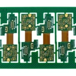
One third of an ounce, about 12 micrometres, is the standard for dynamic flex and for fine line work. It bends to the smallest radius, it etches to the finest feature and it is the usual choice for camera modules, medical catheters and display tails. Half an ounce, about 18 micrometres, is the general purpose flex weight and covers most static bend and moderate current applications. One ounce, about 35 micrometres, is used for static flex where current capacity matters and for rigid flex sections that are not expected to move. Two ounces and above appear on high current flex and on flex heaters, and they are effectively static only, because the foil is too thick to survive repeated flexing. For rigid flex, the flex layers and the rigid layers can and normally do use different copper weights, which is one of the advantages of the construction.
Rolled Annealed Copper and Ductility
Electrodeposited foil, the standard for rigid boards, has a columnar grain structure that cracks under repeated bending. Rolled annealed foil has an elongated grain structure in the plane of the sheet, which gives it far better ductility and fatigue resistance, and it is the normal choice for any flex that will move. It costs more and is available in a more limited range of weights. On a static bend, electrodeposited copper is often acceptable; on a dynamic bend, the choice of foil type matters more than the copper weight itself, and the two should be specified together.
Bending, Fatigue and the Neutral Axis
Bend radius is expressed as a multiple of the total thickness of the flex, and the practical minimum grows as the assembly gets thicker. A single sided flex with a thin coverlay can bend to a very tight radius; a double sided flex with one ounce copper on both sides and thick coverlays cannot. Placing the copper on the inside of the bend reduces the strain range it sees, and a double sided flex should be laid out so that the critical conductors are on the inner surface at each bend. Curved bends, formed rather than creased, distribute the strain far better than a sharp fold, and a bend that is formed once during assembly and then clamped behaves very differently from one that flexes in service. Where the flex must move continuously, give the copper a generous radius, avoid plated through holes and vias in the bend area, and keep the conductor direction perpendicular to the bend line so that the traces are not asked to stretch along their length.
Current Capacity and Thermal Behaviour
A flex tail has no large thermal mass and no heatsink, so current capability is limited by the temperature rise of a thin foil on a thermally insulating substrate. The same current that is comfortable on one ounce rigid copper may be marginal on a half ounce flex trace, and the standard current capacity charts should be applied with a derating for the reduced heat spreading. Where the flex carries power rather than signal, it is common to increase the copper on the power layer, widen the traces, and accept a wider flex. Where it carries a motor or heater current, the trace is often the limiting element in the whole assembly, and the thermal calculation belongs in the specification rather than in a review comment.
Manufacturing Limits
Thicker copper reduces the minimum achievable line width and spacing, because the etch has to remove more material while holding the pattern under the resist. Fine pitch and thick copper are in direct conflict on flex. Thicker copper also requires more adhesive or a heavier coverlay to encapsulate the traces without voids, and it increases the tendency of the finished part to curl. This is why the specification should state the copper weight per layer, the foil type, the coverlay or mask type and thickness, the minimum bend radius, and the number of bend cycles expected in service. A supplier can then confirm whether the combination is buildable before the artwork is released, which is far cheaper than discovering it after the first panels.
How to Specify It
State the copper weight per layer rather than a single figure for the whole stack, and state the foil type for every layer that will bend. Give the bend radius, the bend angle and the expected number of cycles. Give the minimum trace width and spacing that the circuit requires, so that the supplier can check the combination against the etch capability. State the current in the power and ground traces so that the thermal derating can be applied. Finally, keep the dynamic bend area clear of vias, plated holes and stiffeners, and define the stiffener boundaries in the data so that the bend does not fall on a rigid region.
FAQ
What copper thickness is used for dynamic flex? One third of an ounce is the usual choice, with rolled annealed foil, because it bends to the tightest radius and has the best fatigue life.
Can I use one ounce copper on a flex circuit? Yes for static bends and for rigid flex sections that do not move. It is normally unsuitable for a bend that flexes repeatedly in service.
What is rolled annealed copper? A foil with a grain structure elongated in the plane of the sheet, which makes it much more resistant to cracking under repeated bending than electrodeposited foil.
Why does thick copper reduce the minimum line width? The etching process has more material to remove while holding the pattern, so the achievable feature size grows with the copper weight.
How should bends be routed? Perpendicular to the conductor direction, on the inside surface where possible, with a generous radius, and clear of vias, plated holes and stiffeners.
Conclusion
On a flexible circuit the copper weight is a mechanical parameter as much as an electrical one, and the correct value depends on whether the bend is static or dynamic, how tight it is and how many times it will move. Specify the weight per layer, the foil type, the bend radius and the cycle count, and check the combination against the etch and coverlay capability before releasing the artwork. The flex and rigid flex construction limits are listed in PCB capabilities, the routing and bend rules belong in PCB design and layout, and the build process is described in PCB manufacturing. Assembling a prototype PCB assembly with the real bend geometry is the quickest way to confirm the fatigue margin before volume in 2026.