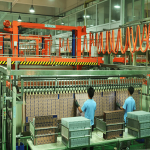
Ceramic Substrates for Thermal Designs
Why Ceramic
A ceramic substrate is used where the electrical and thermal requirements exceed what a polymer laminate can deliver. Ceramics are dimensionally stable, they tolerate high temperatures, they have a high dielectric strength and a low loss at high frequency, and some of them conduct heat far better than any laminate. They are also brittle, they are limited in size, and they cost far more than a polymer board, which is why they appear in specific applications: power modules, high brightness LEDs, high frequency circuits, sensors and anything that has to survive a temperature at which FR4 would decompose.
Alumina
Alumina is the standard ceramic substrate. It is mechanically strong, electrically excellent, cheap relative to the alternatives, and available in a range of purities that trade thermal conductivity against cost. Its thermal conductivity is several times that of FR4 but well below that of a metal, so it is used where the heat flux is moderate and the dielectric performance matters, or where the temperature requirement rules out a laminate. It is normally processed as a thick film or a direct bonded copper structure, and it can be laser machined, which allows the outlines and the holes to be produced with tight tolerance.
Aluminium Nitride
Aluminium nitride conducts heat several times better than alumina, approaching the performance of some metals, while remaining an electrical insulator. That combination is what makes it attractive for high power density modules, where the heat has to pass through an insulating layer. The cost is significantly higher and the material is harder to process, and the surface preparation and the metallisation are more demanding. Where a design needs both electrical isolation and a low thermal resistance, aluminium nitride is often the only practical answer among the ceramics.
LTCC and Thick Film
Low temperature co-fired ceramic is a multilayer technology in which conductors are printed on green ceramic sheets that are then laminated and fired together. It allows a three dimensional structure with buried components, which is useful for compact RF modules and for circuits that need a controlled impedance in a very small area. Thick film on a ceramic substrate is the simpler process, where conductors and resistors are printed and fired on a fired ceramic base, and it is used for sensors, hybrid circuits and power circuits. Both processes have their own design rules, and both produce a board that is difficult or impossible to rework.

Thermal Performance
The thermal path in a ceramic circuit is short and relatively direct, because the substrate conducts and there is no thick dielectric layer in the way as there is on a metal core board. The limits are the metallisation and the die attach rather than the substrate, and the design effort usually goes into maximising the copper area and choosing an attach material with a low thermal resistance. Because the ceramic is an insulator, the isolation is provided by the substrate itself, which means a high voltage can be isolated by a comparatively thin layer, another reason ceramics appear in power circuits.
Mechanical Limits
The material is brittle, so it does not tolerate bending, point loading or thermal shock as a laminate does. The coefficient of expansion is much closer to that of silicon than FR4 is, which reduces the stress on a bonded die but creates a mismatch with the metal hardware around it. Mounting a ceramic substrate requires care: a screw that is over-tightened will crack it, and the surface it is mounted on has to be flat. Where the assembly will see temperature cycling, the attach method and the mounting have to allow for the expansion of the surrounding metal without loading the ceramic.
Assembly and Attach
Components are attached to a ceramic substrate by soldering, by die attach with a conductive adhesive or a solder preform, or by wire bonding. The soldering process is different: the substrate does not flex and it does not absorb moisture, but it also does not spread heat laterally in the same way, so the thermal profile has to be adjusted. Wire bonding requires a metallisation that the bond will adhere to, and the surface finish on a ceramic circuit is chosen for that reason rather than for solderability alone. Rework is limited, and a substrate with an attached die is usually scrapped rather than repaired.
Choosing
Choose a ceramic substrate where the temperature requirement rules out a laminate, where the dielectric performance is essential and a polymer cannot provide it, where the thermal flux is too high for a metal core board’s dielectric layer, or where the coefficient of expansion has to match a bonded device. Choose FR4 or metal core where none of those conditions applies, because the ceramic route costs many times more and constrains the size of the board, the assembly method and the rework policy.
Ceramic and the Mechanical Interface
The interface between a ceramic substrate and the rest of the product is where most ceramic failures originate. The substrate is rigid and brittle, so any load that is applied to it is concentrated rather than distributed, and a mounting that would be unremarkable on a laminate can be destructive. The usual arrangements are a compliant mounting, a thermal interface material that also absorbs movement, or a housing that holds the substrate without clamping it. Where the substrate has to be soldered or bonded to a metal base, the joint has to accommodate the difference in expansion, and a rigid joint between a ceramic and a large metal part is a crack waiting to happen over thermal cycling. The design check is to look at every mechanical interface and ask what will happen when the assembly reaches its maximum temperature and then returns to ambient.

FAQ
What is a ceramic PCB? A circuit built on a ceramic substrate, usually alumina or aluminium nitride, with conductors formed by thick film, direct bonded copper or co-firing.
Which ceramic conducts heat best? Aluminium nitride, which approaches the thermal performance of some metals while remaining an insulator.
Why is ceramic used at high frequency? Because it has low loss and a stable dielectric constant, and because it is dimensionally stable, which keeps a printed circuit’s dimensions accurate.
Can ceramic be reworked? Rarely. The material is brittle and the attach methods are not reversible, so a defective unit is usually scrapped.
When should I use ceramic instead of metal core? Where the dielectric layer of the metal core board is the limiting thermal resistance, or where the operating temperature exceeds what the laminate bonding can survive.
Conclusion
Ceramic substrates solve problems that laminates cannot, at a cost in price, size and process flexibility, so they should be chosen from the thermal, dielectric and temperature requirements rather than as a general upgrade. Match the material to the heat flux, design the mounting so that the brittle substrate is not loaded, and plan the attach method with the assembly house. Substrate options are described under PCB capabilities, the fabrication processes in PCB manufacturing, and the thermal layout belongs to PCB design and layout. Power modules are normally proven through prototype PCB assembly in 2026.