Humidifier Circuit Design: Driving an Ultrasonic Transducer
A humidifier looks like a simple appliance: a tank, a fan and something that turns water into mist. Electrically it contains a mains input, an isolated supply, a high frequency high voltage driver, a microcontroller with sensors, and a set of protections that decide whether the product is safe when the tank runs dry. Getting any one of those wrong produces either a warranty problem or a safety problem.
This article walks through the electrical decisions in the order they should be made, as a reference design exercise rather than a catalogue of parts, from the choice of mist generation method to the layout rules that keep the mains section away from the control electronics.
Choose the Generation Method First
Two approaches dominate small products. An ultrasonic design uses a piezo ceramic disc driven at its resonant frequency, typically around 1.7 MHz, to break the water surface into fine droplets. It is quiet, reasonably efficient and inexpensive, but it is sensitive to water hardness, and it needs a high voltage driver at the transducer.
An evaporative design moves air through a wick and produces no visible mist. It tolerates water quality better and cannot produce wet deposits, but it needs a fan and a larger wicking area, and the perceived humidity output depends on airflow. The choice determines the rest of the block diagram, so it belongs at the start rather than after the enclosure has been designed.
The Power Architecture of a Mains Product
The supply chain for an ultrasonic unit generally runs from an EMI filter and rectifier into an isolated flyback converter that produces a safe intermediate rail, typically 24 volts. From that rail, separate converters produce the voltages the rest of the product needs: one for the fan and pump, one for the control electronics, sensors and radio module, and a boost stage that generates the high voltage for the transducer.
Splitting the conversion this way keeps the noisy high voltage switching separate from the logic supply and allows each converter to be optimised for its load. The flyback is responsible for isolation, which means its transformer, its creepage distances and its feedback path are safety relevant rather than merely functional.
Driving the Ultrasonic Transducer
The transducer behaves electrically as a capacitor, commonly a couple of nanofarads, in series with a resonant structure. Driven at its resonant frequency it presents a low impedance and converts the electrical energy into mechanical vibration; driven away from resonance it simply draws current and heats up.
A full bridge driven as a class D stage is the usual approach because it delivers a square wave with efficient switching. The bridge needs a gate driver with enough peak current to charge and discharge the transistor gates quickly, because slow edges in a high voltage stage produce loss and heat. A resonant matching network of an inductor and a capacitor in series with the transducer performs two jobs at once: it tunes the load to the drive frequency, and it steps the voltage up to the level the transducer requires.
Power is then controlled by varying the duty cycle of the drive rather than its frequency. Keeping the frequency fixed at the transducer resonance avoids exciting audible subharmonics, which would otherwise be heard as a whine. The usable duty range has to be bounded so that the bridge never operates at a duty that leaves the transformer or the transducer in a condition it cannot tolerate.
Water Level, Dry Run and Other Protections
A dry transducer is the failure mode that destroys the product, so the level detection has to be independent of the software. A magnetic float and a reed switch is a dependable combination: the switch changes state when the float drops, the microcontroller sees an interrupt, and a short debounce interval prevents a splashing surface from producing false edges.
A second, electrical indication can be derived from the drive itself. When the transducer is not loaded by water it presents a different impedance, and the voltage across the transducer or the current drawn by the bridge changes accordingly. Using that as a confirmation rather than as the primary sensor gives two independent paths to the same conclusion.
Temperature protection is usually placed in the power section, where a thermistor can respond to a stalled fan or a blocked airflow path. A fan stall can also be detected as an increase in the current drawn by the fan driver, measured across a small sense resistor, which is more direct than inferring it from temperature and reacts sooner.
All of these protections have to converge into a state machine that keeps the product in a defined condition. On a low water event the high voltage has to be removed immediately, and the fan should continue briefly to clear the mist path before the unit finishes shutting down. When the tank is lifted, which is the same event as a lid switch being opened, the same sequence applies, because the user may do exactly that while the unit is running.
Humidity Control and Human Interface
Closed loop humidity control is a straightforward control problem if the sensor is given a chance to work. A digital humidity sensor on the I2C bus provides an absolute measurement, and the controller adjusts the drive level to hold a target. A proportional integral derivative loop with a slow sample rate is sufficient; the loop has to be slower than the sensor response and the mixing of the room air, but fast enough to react to a door opening. Overshoot control matters more than response time, because the user perceives humidity swings as the product working badly.
The interface itself follows the usual pattern for a small appliance: a few buttons, an indicator, a timer, and optional network connectivity. Where a radio module is fitted, its supply and its antenna keep out should be part of the layout review, because a converter running at hundreds of kilohertz next to a 2.4 gigahertz antenna is a predictable source of range complaints.
Safety, EMC and the Layout Rules That Deliver Them
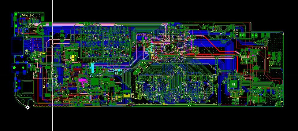
The mains section and the low voltage section are separated by the isolation barrier of the flyback, and that separation has to exist in copper, not only on the schematic. Creepage and clearance distances across the barrier, the cut-out in the board under the transformer, the routing of the feedback path and the placement of the Y capacitor are the items that a safety review will examine. They are decided during layout and cannot be added afterwards.
EMC follows from the same layout. The switching loops of the flyback and the high voltage bridge should be small, the transformer should not be placed where its field couples into the sensor wiring, and the filtering on the transducer drive should be defined by measurement rather than copied. The document that describes the mains section should also state the copper weight and the clearance the board supplier has to hold, because those numbers are part of the safety case and not only of the manufacturing file. Conduction emissions in the lower megahertz range, radiated emissions from the switching nodes and the susceptibility of the sensor and the radio are the tests that decide whether the design will pass, and all of them are cheaper to address before the enclosure is tooled.
FAQ
Why is the drive frequency fixed? Because the transducer only works efficiently at its resonance, and varying the frequency to control power moves the load away from that point and increases loss and audible noise.
Can the mist output be controlled by voltage instead of duty cycle? Duty cycle control keeps the transducer at resonance and is the usual method. Changing the amplitude also changes the operating point of the drive stage.
Is a float switch necessary? Water level detection is necessary. A float switch is one way to do it that does not depend on the transducer drive being present.
What has to be tested for certification? Conduction and radiation emissions, immunity including electrostatic discharge, and the safety requirements that apply to appliances in the target market, all evaluated with the product in its enclosure, using a test programme that covers the assembly as well as the design.
Summary
Humidifier circuit design is a sequence of decisions: choose the mist generation method, build an isolated supply with a safe intermediate rail, drive the transducer at its resonant frequency with a controlled duty cycle, detect water level independently of the software, and keep the mains and control sections separated in copper by the distances the safety standard requires. Each step constrains the next, which is why the electrical architecture has to be settled before the enclosure is drawn.