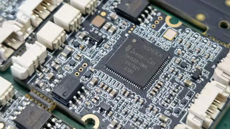
BGA Assembly: Placement, Reflow and How the Joints Are Inspected
A ball grid array is a package whose connections are underneath the body rather than around the edge. That single change of geometry is what makes the package attractive, because it allows hundreds of connections in a small area, and it is also what makes the assembly process more demanding, because nobody can look at the joints afterwards.
The process for these packages is not fundamentally different from any other surface mount assembly. It is the tolerance for error that is different, and the inspection that has to substitute for the eye.
The Package and the Balls
Connections are made by an array of solder balls on the underside, on a pitch that ranges from about a millimetre down to less than a third of that. The package body may be plastic or ceramic, and the balls may be eutectic, lead free or a combination that allows a lower reflow temperature. The ball pitch sets what the board has to support: a finer pitch means smaller pads and less space between them, which means less room for the paste deposit and a narrower process window.
For the assembly house the relevant facts are the pitch, the ball composition, the package size, the thickness and the warpage specification, because all of them affect the profile and the placement.
Paste, Flux and Placement
Two approaches are common. The pads can be printed with paste as for any surface mount device, which transfers a defined volume to each pad. Alternatively, the balls may be placed onto flux, with the solder coming entirely from the package. The first gives more control over the volume and is usual for fine pitch; the second removes the paste printing step from the equation but makes the joint dependent on the ball volume and on the flux activity.
The placement itself is done by a machine that uses vision to align the ball array with the pads rather than aligning the package outline. Placement force matters: too little and the package does not settle into the paste, too much and the paste is squeezed out between adjacent pads. A dipped flux process has a different requirement again, since the ball must touch the flux film without displacing it.

Reflow and the Warpage Problem
The reflow profile has to satisfy two requirements at once. The balls and the paste have to reach the liquidus temperature and form a joint, and the package and the board have to stay flat enough for the balls to remain in contact throughout the process. Package warpage is the reason this is difficult: as the assembly heats, the package and the board expand differently, and a package that is flat at room temperature may curve enough at reflow temperature to lift the balls at the corners.
The consequence of warpage is a joint that appears to be formed and is not, or one that has the right shape but cracks later. The remedies are in the profile and in the materials: a slower soak to equalise the temperature across the assembly, a peak temperature that provides enough time above liquidus without excessive thermal stress, and a board design that supports the package evenly, which places the thermal pad and the copper distribution in the layout domain. Where the package is large, the board thickness and the copper balance beneath it are part of the thermal solution, and the layout of the land pattern should follow the manufacturer recommendation with its thermal pads and its non functional pads if they specify them.
Inspection of Joints That Cannot Be Seen
Optical inspection cannot verify joints underneath the package; at most it can confirm that the package is present and aligned, and that the ball rows visible at the edge appear continuous. The two techniques that are used are transmission X-ray and, for the finest details, computed tomography.
X-ray inspection of a ball array looks for bridges between adjacent balls, for missing balls, for voids within a joint, and for joints that have not collapsed or not formed at all. Voiding deserves a note because it is often misunderstood: some voiding is a normal result of the flux chemistry and is acceptable within a defined percentage of the joint area, while a large void concentrated at the interface is a reliability risk. The acceptance criterion should be stated in the inspection specification rather than decided by the inspector.
The limits of the method also matter. X-ray shows the joint in projection, so two different defects in the same vertical line can appear as one, and the technique is sensitive to the angle and to the magnification. A cross section of a sample from the production panel remains the definitive check, and it is usually reserved for process qualification or for a batch that has shown an anomaly.
Rework and Its Limits
Replacing a large package is possible with localised heating from below and above, but it is a process in its own right: the board has to be preheated to reduce the thermal gradient, the site has to be cleaned and re-balled, and the new package has to be placed with the same accuracy as the original. Every rework cycle applies thermal stress to the board and to the neighbouring components, so a package that fails inspection is often better handled by scrapping the assembly than by reworking it, particularly where reliability is a requirement.
That is a decision worth making before production rather than during it, because the rework policy determines the cost of a yield loss and therefore how much effort belongs in the process development.
Design Choices That Help the Assembly
The land pattern should follow the manufacturer recommendation, since it has been characterised for the package, and the paste aperture ratio should be chosen to deliver a consistent volume per pad rather than the largest possible opening. The solder mask between pads should be designed so that it does not interfere with the deposit.
Thermal relief on the ground pads of a large package is usually the wrong choice, because it impedes heat flow during reflow and worsens the warpage problem; a solid connection is preferred where the assembly process can handle it. Via placement under the package affects the amount of paste that can be printed, so vias that must be in the pad should be filled and plated over rather than left open.
Documentation closes the loop. The assembly drawing should state the package, the pitch, the ball alloy and the profile requirement, and the inspection plan should state what will be examined and with which instrument. Those requirements belong in the purchase order rather than in a conversation, because the incoming boards may come from a different supplier than the one the first prototypes were built with, a risk that component sourcing should address before the order is placed.
FAQ
Can a ball grid array be soldered without paste? Yes, using flux transfer, with the solder coming from the balls. The choice depends on the pitch and the process capability.
Why does the package warp during reflow? Because the materials expand differently with temperature, and the mismatch is largest at the extremes of the package.
Is a void in a joint a defect? Only above the acceptance limit defined for the product. Small scattered voids are normal.
Can the joints be inspected optically? The outer rows can be examined at the edge of the package. The interior requires X-ray.
Summary
BGA assembly depends on four things: a placement that aligns the ball array to the pads, a paste or flux process that delivers a consistent volume, a reflow profile that keeps the package flat while the joints form, and an inspection method that substitutes for the eye. Design choices on the land pattern, the via treatment and the thermal connection under the package decide how much of the process window is available, and the inspection criteria belong in the specification rather than in the inspector judgement.