Odd-Shaped Panel Design for Game Controller Boards
A game controller board is shaped by the shell, the buttons and the way the product is held, so curved edges, narrow necks and asymmetric outlines are normal. The board also carries a main controller, a wireless module, a crystal, connectors and the key contacts. A project that considers only the outline of the single board, without planning the process edge and the way the boards are joined, runs into trouble at printing, placement, reflow and separation.
Why an Ordinary Rectangle Will Not Do
If the board edge comes too close to a component there is not enough room for the machine to hold it. If the panel is not stressed evenly, the board moves during printing and the paste is displaced. If the connections between boards are placed on a narrow neck, separating the panel leaves a burr or concentrated stress there. Whether an odd outline can be built consistently is usually decided before the assembly begins, not during it.
The odd-shaped panel therefore comes before the stencil. Sending the board out as a single outline and treating the panel as a production detail puts the decision in the wrong place.
<img src="https://www.gopcba.com/wp-content/uploads/2020/12/ptt_gallery.jpg" alt="odd-shaped game controller panel during routing” />
Review the Panel Before Making the Stencil
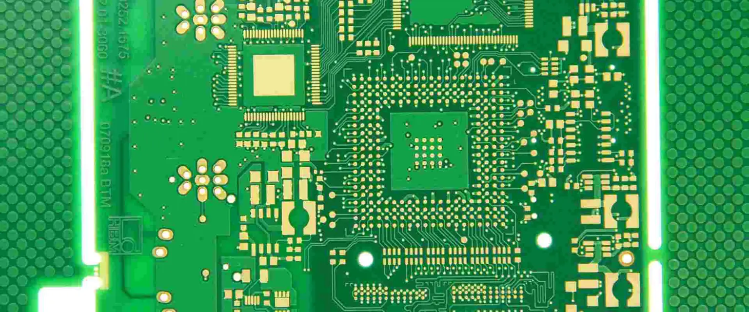
With the Gerber data, the bill of materials, the coordinates and the assembly drawing, the customer also states whether the boards are delivered singly or as a panel, which outline dimensions are critical, where the key contact areas are and what the shell requires. If a panel drawing already exists, the process edge width, the tooling holes, the connection positions and the separation method are checked against it. If only the single board is available, a panel design is evaluated from the production and delivery requirement.
Packing an odd shape more densely is not automatically better. A gap that is too small leaves no room for the router; too few connections between the boards lets the panel deform during production; too many connections adds separation time and leaves residue on the edge. Connections placed near the antenna area, a connector or a key contact are avoided because the stress of separation can affect the component and the copper underneath.
The review is made from the customer file, the board thickness, the outline and the distribution of the components, and any dimension or structure that cannot be confirmed is raised as a question before the stencil and the programme are prepared.
Protecting the Key Contacts
The metal key contacts or the conductive rubber pads on a controller board are sensitive to the state of the surface. They usually carry no components, which is exactly why paste, flux or other contamination can reach them during printing, reflow and handling. The stencil openings and the handling instructions keep clear of those areas, and the board inspection looks specifically for residue there.
During assembly, the placement coordinates have to agree with the actual panel orientation. The wireless module, the main controller, the crystal and the polarised parts are on the first article check list, and the small connectors that both make an electrical joint and locate the shell are watched for how flat the body sits and whether the orientation is right.
The first article is not only a count of the parts present. The flatness of the board, the stability of the support and the distance between the components and the board edge are all part of it. Where the paste is offset in one region, the fixture and the panel deformation are examined before the stencil is changed.
Inspect the Panel Before Separating It
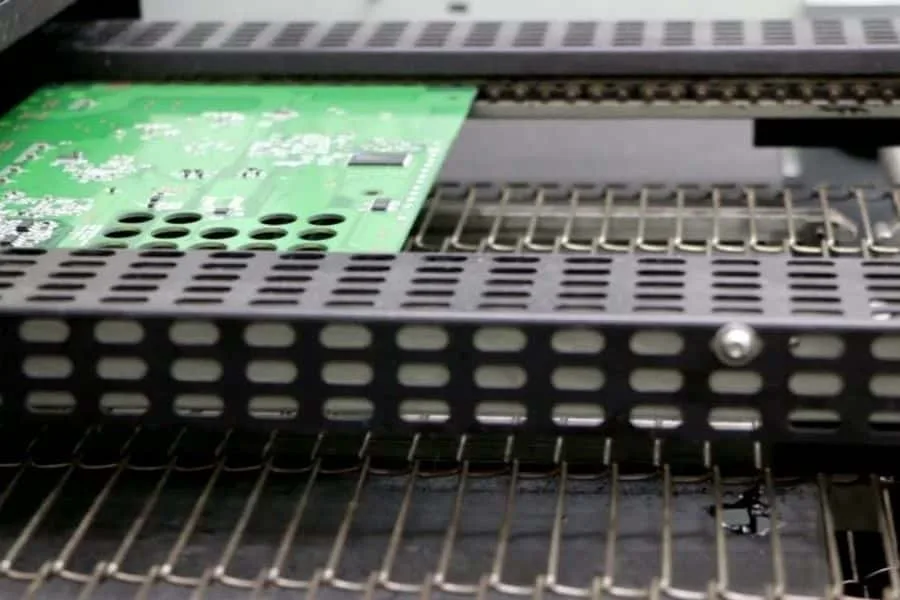
After reflow, optical inspection covers the missing parts, the offset, the bridging, the tombstoning and the visible joints. Where the customer requires a check of a wireless module or a device with hidden joints, the method is evaluated against the board type.
Separating the whole batch before the joints have been confirmed is not advisable. A panel is easier to inspect as a panel, and keeping the boards together reduces the chance of mixing different boards during handling. The first panel that passes also becomes the reference for the separation parameters and for the visual acceptance of the edges.
Controlling the Separation
An odd outline is normally separated with a router rather than with a straight cut. Before the run, the path, the tool diameter, the direction of travel, the connection positions and the fixture support are confirmed. The path must not touch a component, and the extraction has to remain effective so that dust does not settle on the key area or inside a connector.
After separation the edges are checked for integrity, burrs, chipping, remaining breakout tabs and critical dimensions. Where a component sits close to the edge, it is checked for movement, cracking and stress on its joints. If the same position chips repeatedly, the connection structure, the condition of the tool, the direction of the cut and the material are examined rather than the edges being dressed by hand one board at a time.
The routing programme is part of the production data, so a change to the outline or to the panel means the programme is re-evaluated rather than adjusted by the operator.
Programming and Function After Separation
Once the boards are separate, the programming and the functional test follow the customer requirement: the program revision, the programming interface, the supply conditions, the wireless connection method, the key test steps and the acceptance criteria. Where the product has to be tested inside its shell, the question of who supplies the shell, the key assembly and the fixture is settled in advance.
A key that does not respond is not automatically a soldering problem. Contamination on the contact, a part of the assembly that is not seated, a mapping error in the program and a fault in the test connection all produce the same result. The first question is whether the fault stays with one key, one reference designator or one batch, because that answer decides whether the board, the component or the program is examined next.
Our SMT assembly line handles the odd-shaped panels, PCB manufacturing produces the boards and the panel, and the programming and functional testing are covered by PCBA testing.
Panel Configuration and Delivery
`r`n
A second decision follows the outline decision: whether the customer wants the boards delivered separately or as a panel. Delivering as a panel keeps the boards protected during transport and lets the customer run its own assembly with the panel intact, while delivering separately reduces the handling on the customer side. Both are reasonable, and the answer changes the process edge, the connections and the packing.
`r`n
When a panel is delivered, the drawing that accompanies it states the outline, the connection positions and the direction of the individual boards, because a supplier downstream that has to separate them will otherwise guess. Where the boards are delivered separately, the edge quality becomes part of the acceptance criteria in a way that it is not when the customer separates the panel itself.
FAQ
Can an odd outline be assembled without a panel? It can be produced, but the assembly is far more stable with a process edge and defined support, which is what the panel provides.
What decides how many tabs a panel has? The stiffness the panel needs during production against the time and the edge quality the separation requires.
Why inspect before separating? Because a panel is easier to inspect as one unit and the boards are less likely to be mixed during handling.