LGA Soldering and RF Test on a Positioning Terminal Board
A positioning terminal board may start up and communicate normally and still take too long to acquire satellites, receive a weak signal or report an unstable position. Taking the module off the board at that point is a common reaction and a poor one: it may not fix anything, and it exposes the board to a second thermal cycle that carries its own risk. The same symptom can come from a program or configuration mismatch, from the test environment, from the antenna, from a wrong component in the radio path, from the crystal, or from the joints under the module.
Reproduce Before Reaching for the Iron
When a customer reports an anomaly, the useful information is the board revision, the program revision, the antenna model and how it is connected, the supply conditions, a description of the test location, the number of boards affected and the data from a board that behaves normally. A message saying only that the signal is poor leaves the factory unable to tell an isolated board from a batch, or a product fault from a change in the test method.
The re-test compares a normal board with the suspect board under the same program, the same antenna, the same supply and the same fixture. If the result recovers when the cable or the antenna is exchanged, the connection is investigated further. If the anomaly follows the same board every time, the investigation moves onto the board. Following that order removes the repairs that were never justified.
Checking the Radio Path in the Data
The project needs the Gerber data, the bill of materials, the placement coordinates, the assembly drawing, the program, the test method, the quantity and the lead time. The bill of materials should name the positioning module, the crystal, the filters, the radio connector and the matching components by full part number rather than by a general description.
During the review, the module orientation, the reference designators, the positions that are not populated and any substitution are checked against the coordinates and the bill of materials. The small components in a radio path often look alike, and a wrong value or a wrong type will still allow the board to run while changing how it receives. The assessment of the manufacturing data is made from what the customer supplies; anything that requires a judgement about the parameters or the design is referred back for confirmation.
What Matters in LGA Soldering
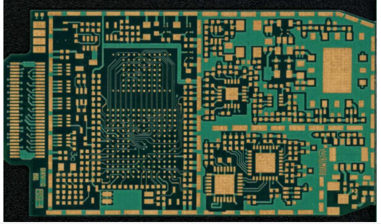
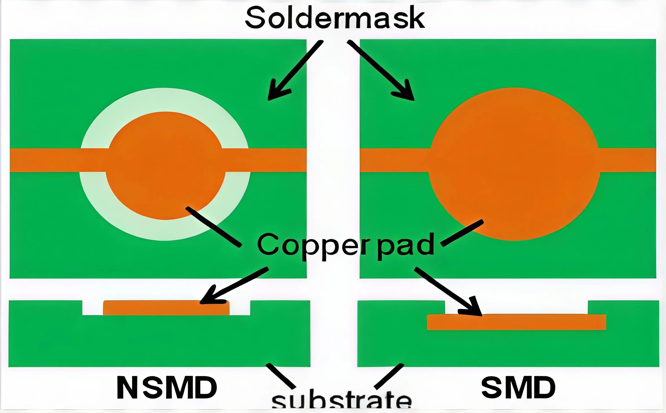
The module is usually supplied in a package with pads underneath, so the joints cannot be confirmed from the outside once the part has been placed. The stencil opening is evaluated against the pad structure so that the volume and the offset of the paste are controlled. Too little paste leaves a joint that never forms locally; paste that is uneven across the pad lifts one side of the module.
The placement programme is checked for the pick position, the angle of the part, the origin of the coordinates and the placement height. A module that lands away from the centre of its pad can look acceptable after reflow while the connection underneath is wrong. The first article confirms the position of the module body and the orientation of the parts around it before the batch continues.
The reflow profile is evaluated from the board structure, the thermal mass of the module, the paste and the customer requirement. When something goes wrong, the print record, the first article record and the reflow record are read before any decision is taken about the hidden joints, which is how the vague conclusion that the module was not soldered properly is avoided.
Shielding and the Antenna Interface
Some boards carry a shielding frame or a shielding can. Where it is fitted, how it is soldered and whether it interferes with a neighbouring part all affect the later assembly. If the shield is present during one measurement and absent during another, the two sets of data are not comparable and should not be treated as though they were.
The antenna connector is checked for the position of its body, the state of its joints and the condition of the mating interface. A test cable that has been used many times develops losses and intermittent contacts of its own, so an RF test needs a fixed cable, a fixed fixture and a fixed procedure, and only data collected under those conditions can be compared with anything.
Deciding Whether to Look Under the Module
If the anomaly follows the same board under the same program and test conditions, and the antenna, the cable, the supply and the configuration have all been excluded, an examination of the hidden joints is evaluated from the failed reference designator, the board structure and the way the fault behaves. The scope of that examination comes from the customer requirement rather than from a general rule.
Where the joints are found to be at fault, the rework is followed by the full sequence again: the visual check, the basic communication test and the radio function test. Saying that the module has been re-soldered is not evidence that the board works. Where the joints turn out to be sound, the investigation continues with the radio path components, the crystal, the supply ripple and the program settings.
If the same position fails repeatedly in production, the stencil condition, the print support, the component packaging, the placement position and the reflow conditions are all examined so that the corrective action is something that can be verified later rather than an opinion.
Information Kept for a Repeat Test
The delivery record states the board revision, the program revision, the programming state and the test conditions. If the customer later changes the antenna, the enclosure or the program, that record is what allows the question to be answered as to whether the problem lies in the manufacturing stage or in a change to the product configuration.
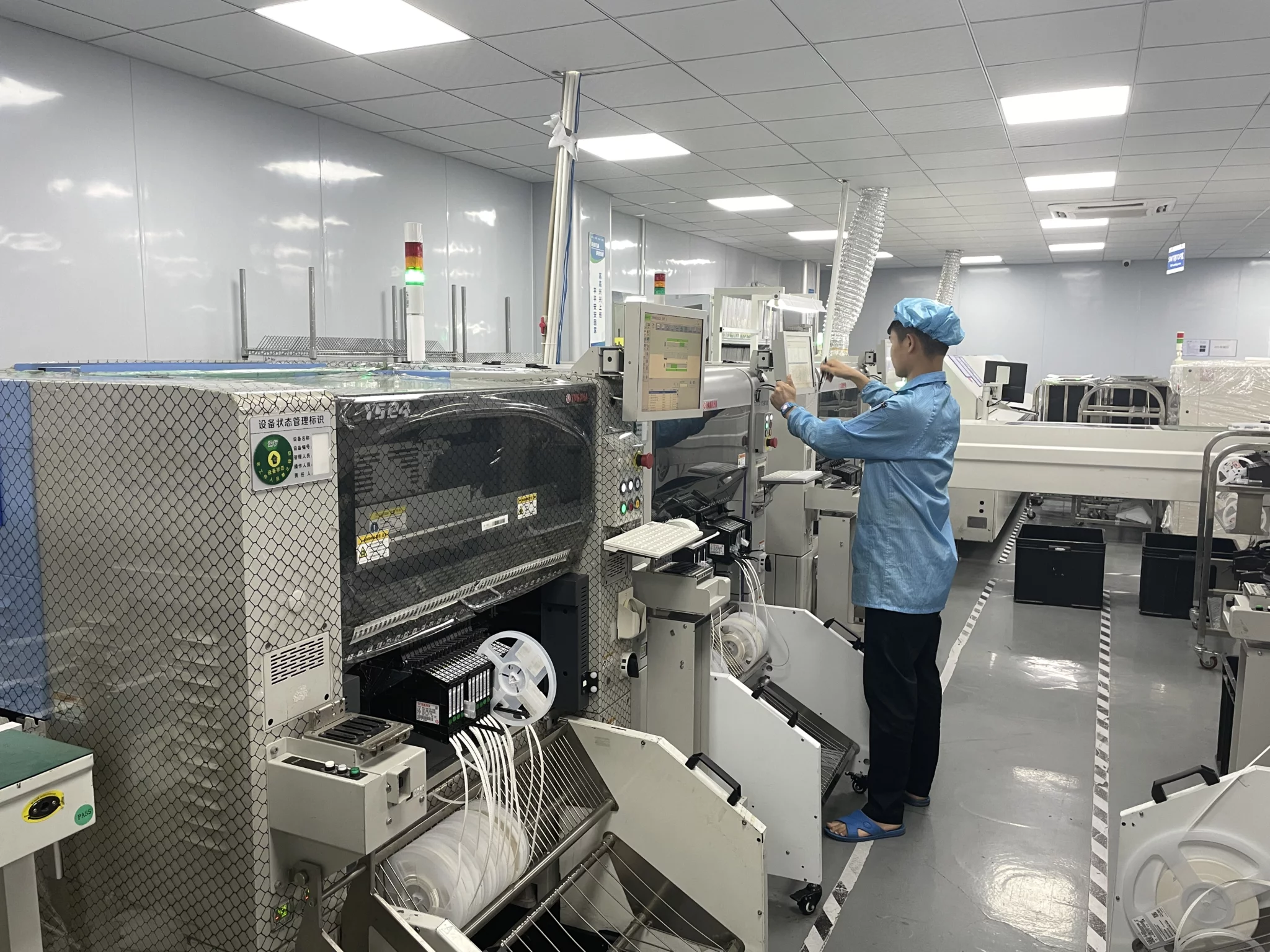
Our SMT assembly lines place the LGA module, component procurement controls the material in the radio path, and the programming and radio testing are run under the records held by quality management.
Where the Effort Should Go First
`r`n
Most of the time saved on a case like this comes from order rather than from equipment. Reproducing the fault under fixed conditions takes an hour and can remove a repair that would have taken a day and a thermal cycle. Reading the print and reflow records before touching the board costs minutes. The examination of a hidden joint, by contrast, is slow and is worth doing only once the cheap explanations have been eliminated, which is why it sits at the end of the sequence rather than at the start.
`r`n
That order also produces a better record. A case that closes with a measured difference between two boards, and with the conditions under which the difference appeared, can be compared with a future case. A case that closes with a module replaced leaves nothing behind except a board that seems to work.
FAQ
Can a weak signal be diagnosed as a soldering fault immediately? No. The program, the antenna, the supply and the test conditions are excluded first, because each of them can produce the same symptom.
Why not simply replace the module? Because it may not be the cause, and the second thermal cycle introduces a new risk to the board.
What makes radio test data comparable? The same cable, the same fixture and the same procedure, recorded with the board so that a later measurement can be checked against it.