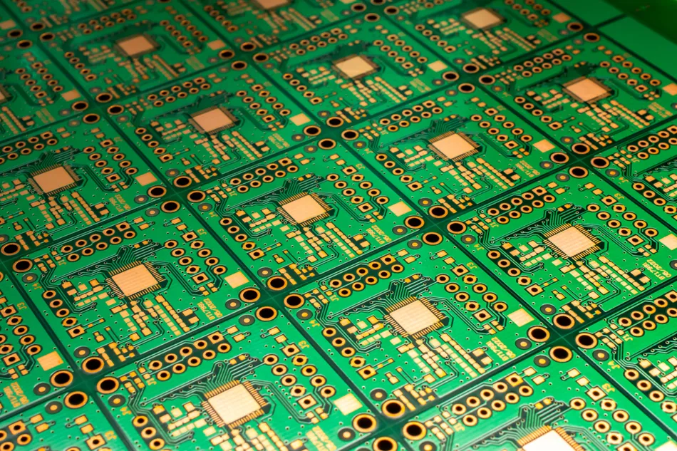
Drone Flight Controller PCBA Assembly and Sensor Test
A drone flight controller board is compact and carries a large number of direction sensitive devices: the processor, the inertial sensors, the barometric sensor, memory, a crystal, the power section and several connectors. The packages are small and closely spaced, and some of the sensors have a defined orientation that the board has to respect. Orientation, soldering and the programme revision are connected to each other, because a sensor placed at a rotation produces test results that look like a software fault when the cause is on the board.
What the Order Needs
The Gerber data, the bill of materials, the placement coordinates, the assembly drawing, the quantity and the delivery date are the base set. The bill of materials names the processor, the inertial sensors, the pressure sensor, the crystal and the power devices by full part number and package.
The assembly drawing marks the direction sensitive parts and the positions of the interfaces, because the legend printed on the board is not a reliable substitute: it is often small enough to be obscured by the component that has been placed over it. Where programming is included, the programme file, the device type, the programming interface and the method of reading the revision back are supplied, and where a sensor test or a calibration is required, the customer defines the orientation of the board during the test, the procedure and the acceptance condition.
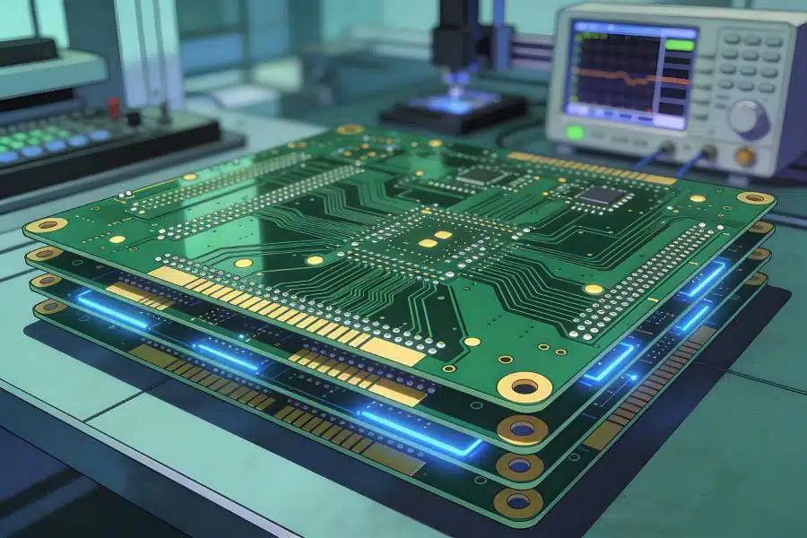
Getting the Small Sensors Into the Process
At intake the bill of materials, the coordinates, the assembly drawing and the physical packaging are checked against each other. Some sensors are almost symmetric and their orientation marking is small, so the specification and the direction of the tape have to be used together to confirm which way the part is facing rather than the appearance of the body alone.
After printing, the area, volume, height and offset of the paste are measured. If the pads of the sensors or the fine pitch processor show a repeated print anomaly, the stencil, the support under the board and the printing state are examined in that order.
The placement programme is checked for the component angle, the nozzle and the vision recognition. When a reel is exchanged or material is added during the run, the orientation is confirmed again, because two reels of the same part can be wound in different directions and the size of the reel proves nothing about the part on it.
What the SMT First Article Covers
After the first board has been placed and reflowed, the processor, the inertial sensors, the pressure sensor, the crystal and the interface devices are examined. Optical inspection catches the missing parts, the offset, the reversed parts and the visible joint anomalies, and a machine alarm is reviewed by a person rather than accepted or cleared on the strength of the image.
For a device with joints beneath the body, the extent of any further examination is agreed with the customer. The fact that a board powers up is not a reason to skip the check of the joints and the orientation, because a sensor mounted at the wrong rotation does not prevent the board from running.
If the same sensor keeps showing an offset, the paste, the coordinates, the pick position and the reflow state are reviewed. If the orientation is wrong, the assembly data, the machine programme and the direction of the material packaging are all examined, since the error can originate in any of the three.
<img src="https://www.gopcba.com/wp-content/uploads/2026/08/Flashlight-PCB-board-powering-LED-strip-and-modules-768×561-1.webp" alt="inertial sensor placed on a compact flight controller board” />
Connecting the Programme to the Sensor Test
After programming, the hardware and the programme revision are confirmed before the write, and the revision or the checksum is read back afterwards using the method the customer provides. The sensor test can then be carried out on a fixture that holds the board at a fixed orientation, verifying the readings and the communication state that the customer specified.
When the test fails, the possibilities are the programme, the supply, the soldering, the sensor orientation and the connection, and they are separated in that order because the cheapest explanations come first. A board that has been repaired, reprogrammed or given a new sensor repeats the corresponding test rather than being released on the basis that the component has been put back.
A simple power-up check is not accepted as a substitute for the functional and acceptance conditions the customer defines, since a board that runs is not necessarily a board that measures correctly.
From a Small Batch Into Volume
The first production run of a flight controller board is worth carrying out as a small batch so that the material, the stencil, the orientations, the programme and the test flow can all be verified together. The Gerber data, the bill of materials, the coordinates, the programme and the test documentation that are confirmed in that batch become the production revision, and later orders are compared against them rather than against a set of verbal notes.
Once the order is in volume, different hardware and programme revisions are kept in separate flows. The finished boards are packed in antistatic material with the edge connectors and the sensor area protected from compression, because a board that is damaged in transit fails in a way that looks like a design problem. Our SMT assembly lines build the board, PCBA testing covers the programming and the sensor checks, and the records are held under quality management.
Handling, Packing and the Record Behind the Batch
Every batch of a flight controller board is documented from the incoming material to the finished goods. The material lot numbers, the stencil revision, the placement programme revision, the reflow profile, the programming revision and the test result are recorded against the order, so that a question raised months later is answered by reading the record rather than by reconstructing the process from memory.
Handling is part of the specification rather than a housekeeping detail. Boards that carry exposed sensors are held by the edges, and the stack height, the separation between boards and the force applied to the assembly are controlled, because a board whose mounted sensor has been squeezed can still pass a power-up check and then deliver a reading that is quietly wrong.
The programme file and the customer’s test specification are frozen with the production revision. When the customer issues an update, the batch from which it takes effect is stated in writing and the superseded revision is withdrawn from the line, since a board programmed with the previous file cannot be picked out of a mixed group afterwards.
A small batch is therefore the natural entry point for a new design, because it confirms the Gerber data, the bill of materials, the coordinates, the stencil and the test flow in one pass. Customers who want that review extended to the artwork can discuss PCB design and layout and the industrial PCBA route with the engineering team before the volume order is placed.
FAQ
Why is the sensor orientation so important? Because a sensor placed at a rotation still powers up and still communicates, and the error only appears in the behaviour of the product, which makes it look like a software problem.
Can the board legend be used to judge orientation? Not reliably. The legend may be small or hidden under the component, so the assembly drawing and the packaging direction are used.
What is tested after programming? The revision is read back, and the sensor and communication checks follow the customer’s procedure on a fixture that fixes the board orientation.