High Frequency Material Selection for Multilayer Boards
The choice of laminate for a multilayer board used to be a decision about the operating temperature and the cost. For boards carrying high speed interfaces it has become an electrical decision, because the material contributes a measurable part of the total loss of the channel and the loss budget has to be met at the far end of a long trace. High frequency material selection is therefore part of the signal design rather than a purchasing preference, and it constrains the stack-up before the first net is routed.
What the Material Contributes
The dielectric constant of the laminate determines the impedance of a trace of a given width and spacing, and therefore determines the geometry the layout has to use to hit an impedance target. A higher constant produces a narrower trace for the same impedance, which allows denser routing but increases the conductor loss.
The loss tangent determines how much of the signal is absorbed by the material as it travels. At low frequencies its contribution is small enough to ignore; at the data rates used by modern high speed interfaces it becomes a significant fraction of the total loss, and reducing it is the main reason for choosing a specialised material.
The third contribution is stability. The dielectric constant of a material changes with temperature and with frequency, and a material whose value drifts under operating conditions changes the impedance of every controlled trace on the board. For a design with a narrow impedance tolerance, that drift is part of the budget.

Reading a Material Datasheet
Materials are specified with a dielectric constant, a loss tangent and a set of mechanical and thermal properties, and each of those numbers is quoted at a particular frequency and a particular method. Comparing two materials from numbers taken at different frequencies is a common error, because the values move with frequency and the ranking can change.
The second point to establish is the insertion loss behaviour rather than the raw loss tangent. The loss of a channel depends on the geometry as well as the material, and a material with a slightly better loss tangent may produce a worse channel if it forces a narrower trace or a different stack-up. The useful comparison is on the channel, not on the material in isolation.
The third is the processing consequence. A high performance material is not a drop in replacement for an ordinary one: the drilling parameters, the desmear process, the lamination cycle and the surface preparation all change, and a material that is not processed on its own recipe will produce a board that measures worse than it should.
The Stack-up Consequences
Choosing a material sets the dielectric thickness that will be used, because the impedance target and the trace geometry are solved together. A thinner dielectric allows a narrower trace for the same impedance, which helps routing density and increases the loss per unit length, so the stack-up and the routing plan are developed at the same time.
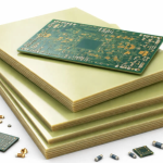
Where the design mixes ordinary and high speed interfaces, a common approach is to use the high performance material only for the layers that carry the high speed signals and a standard material elsewhere. That is a hybrid stack-up, and it reduces the cost and the processing difficulty at the price of a more complicated lamination sequence. Whether it is worth it depends on the proportion of the board that carries the fast interfaces and on the cost difference between the materials.
The hybrid arrangement also introduces a mechanical consideration. Materials with different properties expand at different rates, and a stack that mixes them has to be designed so that the difference does not produce warpage or stress at the interface. The lamination cycle is written for the combination rather than for either material alone.

Verification on the Finished Board
The value a design assumes has to be verified on the product. A test coupon travels with the panel and the impedance of the controlled structures is measured and reported, which allows the finished board to be compared with the value the analysis used. Where the measurement differs, the difference is either in the process or in the assumption, and both are worth knowing.
For a high frequency design the coupon can also carry a transmission line whose loss is measured, which gives a direct comparison against the loss budget. A board whose measured loss exceeds the budget is a board that will fail its link margin, and finding that on the coupon is preferable to finding it in a system test.
Deciding What Is Needed
The starting point is the loss budget rather than the material list. Establishing how much loss the link can tolerate, and how much of it is consumed by the connector, the package, the via and the copper, leaves the amount available for the dielectric, and the material follows from that. A material chosen without the budget in hand is a material chosen on reputation.
The second input is the availability, which for specialised laminates is a genuine constraint on the schedule. Where a material is committed or has a long lead time, the design is better adjusted while the stack-up is open than discovered when the order is placed. Our PCB manufacturing team supports the material decision, the capability limits are stated on PCB capabilities, the design work sits with PCB design and layout, the material is sourced through component procurement, and the assembly and test follow through SMT assembly and PCBA testing.
Where the Decision Is Made
The material decision belongs in the stack-up conversation, which means it happens before the layout is drawn rather than after. Once the dielectric thickness and the material are fixed, the trace geometry needed for each impedance is fixed as well, and the routing density the design can achieve is determined. Changing the material after the layout is complete means changing every controlled trace on the board.
The exception is the design that starts from an existing platform. Where the stack-up already exists and the requirement has not changed, the material is inherited rather than chosen, and the work is to confirm that the existing structure still meets the loss budget for the new interfaces. That confirmation is worth performing explicitly, because a platform that was designed for a slower interface may not have the margin that the new one needs.
The third case is the one that causes the most difficulty: a design that has been produced without a loss budget at all. In that situation the material has been chosen on reputation, the impedances have been set from a rule of thumb and the margin is unknown, and the first evidence of a problem appears in a system test that is difficult to diagnose because every element of the channel is a candidate.
Cost and Availability Together
The cost of a specialised laminate is a real consideration and it is not the only one. A material that is inexpensive and available will produce a board on a predictable schedule, while a material that is marginally better and constrained will produce a board whose delivery date depends on the allocation of a scarce resource. For most programmes the second is the worse outcome, and the judgement is worth making explicitly rather than by default.
The practical test is to ask what happens if the material is not available. If the answer is that the design can move to a slightly lossier laminate with a small reduction in the link margin, the risk is manageable. If the answer is that the product does not work, then the material is a single point of failure and the design should say so, so that the material can be secured before the order rather than after it.
FAQ
Is a lower loss tangent always better? Not in isolation. The channel loss depends on the geometry the material forces as well as on the material itself.
What is a hybrid stack-up? One that uses a high performance material only on the layers carrying the fast signals and a standard material elsewhere.
How is the material verified? From a coupon that travels with the panel, measured for impedance and, where the design requires it, for transmission line loss.