
Medical Measurement PCBA: Data, Material and Inspection
Boards that are built into measuring equipment are not necessarily the most complex boards a factory will assemble, and they are frequently among the most demanding. The product exists to produce a number that someone will act on, and the small differences that a consumer device absorbs — a tolerance here, a residue there, a joint that is marginal — can change that number or make it unstable.
This is why medical measurement assemblies are managed around three things rather than around throughput: the accuracy of the data package, the material consistency of the sensitive devices, and the inspection that confirms both.
The Data Package and Where It Usually Falls Short
The package begins with the fabrication data, the bill of materials, the coordinates, the panel arrangement and any statement of special process requirements. In this class of product the omissions are predictable, and they are worth checking for explicitly before production starts.
A part number with an unclear suffix is one of them: two variants of the same device can differ in grade, temperature range or package, and the difference matters in exactly the circuits this product contains. An undefined orientation for a sensor interface, a connector whose height interferes with the mechanical assembly, an unclear substitution rule for a precision resistor or capacitor, and insufficient test points for the verification that follows are the others.
Each of these is trivial to resolve at the enquiry stage and expensive to resolve once the boards are built. The useful question is not whether the data is complete in a general sense but whether every device whose parameters matter has been identified unambiguously enough for someone else to buy it and place it.
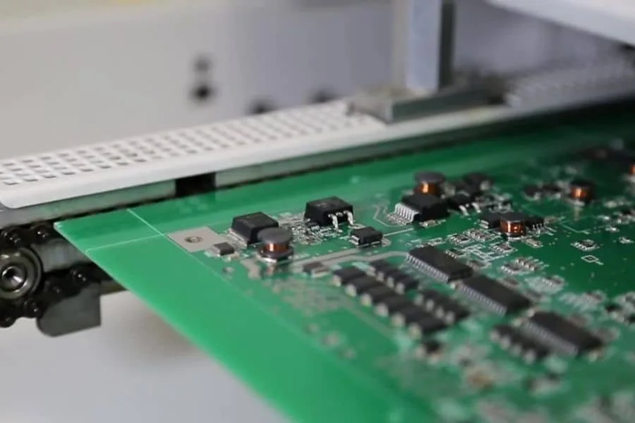
Material Consistency
Operational amplifiers, voltage references, converters, crystals, sampling resistors and filter capacitors are the devices that decide what the instrument measures. Even where two parts share a footprint, they may differ in offset, noise, tolerance, temperature coefficient or start-up behaviour, and a change in any of them can appear as a change in the reading.
Supply in the region is fast and varied, which makes a substitution tempting when a part is short. The rule for this class of product is that a substitute is proposed with its differences stated and confirmed by the customer’s engineering team, and that the decision is recorded against the project. Passives may follow a general rule; the analogue front end, the reference and the precision sampling devices should not be changed by a purchasing decision.
Moisture sensitivity belongs to the same discipline. A device that has been exposed beyond its floor life and reflowed without drying may show no immediate defect, and the damage it has sustained becomes visible later as drift or as an intermittent fault that cannot be reproduced.
Printing, Placement and the Reflow Profile
These boards carry fine pitch devices, small passives, display connectors and sensor interfaces, and the joints that result from an unstable print are the ones that produce the faults nobody can reproduce: a joint that is marginally connected behaves differently as the assembly changes temperature.
The stencil aperture is derived from the pad geometry and the material thickness, and printing is verified by measurement rather than by appearance, with solder paste inspection covering area, height and volume where the equipment allows it. Placement is confirmed for part number, polarity and offset, and the thermal profile is written for the assembly as a whole rather than for the largest or smallest device on it.
After reflow, the first article confirms part number, orientation, position and joint condition. Optical inspection then covers missing parts, wrong parts, displacement and bridging, with manual review added for the areas where reflection or shadow makes an automated decision unreliable. Boards of this type are often built for engineering verification or for a pilot, and a manufacturing defect that reaches that stage is interpreted as a design problem, which costs far more time than the defect itself.

What the Inspection Is For
The inspection stage is not a search for defects of any kind; it is aimed at the failure modes this product has. Visible joint defects are looked for as they would be on any assembly, and beyond that the interest is in the positions where a hidden fault would present as a measurement error: the analogue front end, the reference circuit, the supply regulation and the interfaces to the sensors.
Where the equipment and the requirement justify it, X-ray sampling is used on the devices whose joints cannot be seen. Where a position has been soldered by hand, microscopic examination is added, because hand work is where variation enters a process that is otherwise controlled. The acceptance criteria and the equipment used are recorded, so that the inspection of the next batch means the same thing as the inspection of this one.
Testing and the Limits of a Factory Test
An assembly test covers the supply, the regulated outputs, the sensor inputs, the display interface, the communications, the keys and the indicators, together with the programming where the order includes it. Where measurement accuracy is involved, the test method and the acceptance values are defined by the customer, because the factory can confirm that the board behaves as the procedure says and cannot invent the accuracy requirement for the product.
What is worth insisting on is that the test method is written down precisely enough to be repeated. A procedure that asks whether the reading is correct will produce different answers from different operators on the same board, and a test whose result depends on who performed it cannot support a release decision.
Protection and Delivery
Boards fitted with display sockets, sensor connectors, ribbon connectors and precision devices need packing that protects them from static, pressure and moisture. Trays that hold each board separately, antistatic bags, dividers and labels that are legible without opening the packing all reduce the cost of the next stage, whether that is the customer’s incoming inspection or their own assembly line.
The work is performed as SMT assembly, with pin-in-hole positions handled through through-hole assembly, the material side through component procurement, the verification through PCBA testing, the criteria and records under quality management and the medical product context under medical PCBA.
Working With the Customer’s Verification Stage
For a measuring product, the factory test is the beginning of the customer’s verification rather than the end of it. The boards that leave will be characterised, compared against references and possibly used in trials, and anything the assembly records at that point saves the customer from reconstructing it later.
That is why the records worth keeping are the ones that make a later comparison possible: the hardware revision, the programme version, the lots used for the sensitive devices, the inspection result and the test data. A board whose history is unknown cannot be compared with one built six months later, and any difference between the two batches then becomes a question about material, process or design with no evidence available to answer it.
Where the customer intends to write correction values, it helps to agree in advance which positions are adjusted, whether the correction is held in the assembly or in the instrument, and whether replacing a component invalidates the calibration. Those three answers decide whether a repair is a repair or a recalibration.
FAQ
Why is material consistency more important here than on a consumer board? Because the parameters that distinguish one part from another are the parameters the instrument measures, so a change of device can appear as a change in the result.
Can a substitute be accepted automatically if the package matches? No. The difference has to be assessed against the function of the position, and the decision recorded against the project.
What does the factory test confirm? That the assembly behaves as the written procedure and limits require; the measurement accuracy specification itself comes from the customer.