Power Supply PCBA: Thermal Design and Safety Spacing
A power board is judged by a different standard from a control board. Soldering it correctly is the beginning rather than the end of the requirement, because the product has to survive continuous operation in an enclosure, at temperature, with mains voltage on one side of it and a low-voltage control section on the other. Thermal design, insulation spacing, current-carrying paths and test coverage therefore have to be settled before the first board is built, when they can still be changed cheaply.
Projects of this kind are common in industrial equipment, power modules, control cabinets and instrumentation. They combine AC input, DC output, power devices, transformers, inductors, electrolytic capacitors, heatsinks, relays and terminal blocks on one assembly, and a power supply PCBA cannot be processed as though it were an ordinary surface mount board with a few large parts added.
Heat Is Designed In, Not Added Afterwards
Every device that carries current produces heat, and on a power board the list is long: power MOSFETs, rectifiers, regulators, inductors, transformers, sense resistors and the electrolytic capacitors that age fastest when they run warm. Where the copper area, the thermal path to the heatsink, the airflow and the component heights have not been considered together, the result is a board that passes a short bench test and drifts out of specification in the cabinet.
The layout decision matters most, because it is the one that cannot be corrected later. Copper that is too thin under a power device raises the junction temperature before any assembly step begins. Devices placed in the shadow of a tall transformer receive less air than the calculation assumed. Capacitors sited next to a hot component age at a rate the designer never intended.
Assembly then has to preserve whatever the design achieved. That means the thermal interface is treated as a critical dimension rather than as an accessory, and the mounting hardware is specified rather than improvised.

Heatsink Assembly and the Interface
Fixing a heatsink is a mechanical operation with electrical and thermal consequences. The interface between the device and the metal has to be flat, clean and covered with the intended material, whether that is a thermal pad, a paste or an insulating sheet. A pad that is the wrong thickness, a screw tightened unevenly, a device that sits at a slight angle: each raises the thermal resistance that the design assumed would be low.
The electrical side is just as important. Where the tab of a device is live, the insulating sheet is the only thing separating it from a grounded enclosure, and its integrity has to be verified rather than assumed. Where the tab is common with a rail, the mounting may be direct, but then the heatsink itself becomes part of the circuit and the spacing rules in the next section apply to it as well.
Mechanical stress belongs in this discussion too. A large heatsink bolted to a small package can load the solder joints around it, and a terminal tightened during installation can transfer that load to the board. Recording the assembly sequence, the torque and the hardware used is what makes the difference between a unit that survives transport and one that arrives with a cracked joint.
Creepage Distance and Clearance on the Built Board
Insulation spacing is a design topic that becomes a production topic. The creepage distance along a surface and the clearance through air between the high-voltage and low-voltage sides are fixed by the layout, and no amount of careful assembly can recover a distance that was never there.
What assembly can do is erode it. Solder residue, flux left on the surface, a terminal lead that is trimmed too long, a wire routed across a barrier, a heatsink that shifts a millimetre towards a live pad: each of these reduces the effective spacing of a board that was correct as drawn. The controls are ordinary ones, which is why they are easy to overlook on a short run: no-clean chemistry chosen to match the insulation requirement, a defined trim length, a routing rule for internal wiring, and a visual check of the barrier region at the end of the line.
For products that will be certified, the inspection criteria should be written down before the pilot rather than after the first sample is submitted. A requirement discovered during certification is a redesign; the same requirement discovered during a first article check is an adjustment.
High-Current Paths and Inserted Joints
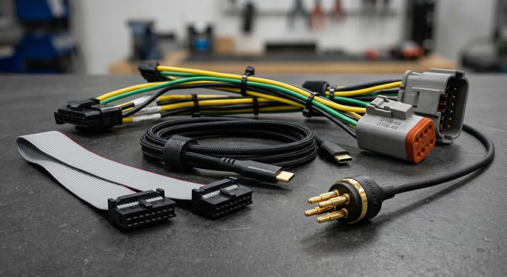
Current does not travel only through the copper. It travels through terminal blocks, relay pins, connector contacts and every solder joint in between, and each of those is a place where resistance can be higher than the design intended.
On a power board the inserted devices usually carry the mechanical load as well. Terminals, electrolytic capacitors, inductors and transformers are soldered and then mated, pulled or clamped, so their joints are assessed for penetration, fillet shape and mechanical support, not merely for continuity. A joint that measures correctly with a meter can still be the weakest point of the unit after a year of thermal cycling.
Assembly conditions decide much of this. A board with heavy copper and large thermal mass needs a soldering process that reaches the joint properly without overheating neighbouring parts, and the operators need to know which devices are heat-sensitive. Where a wave or selective process is used, the direction, the pallet and the preheat all affect whether the barrels fill.
Test Coverage: Function, Temperature and Burn-In Test
A functional check confirms that the output is present and correct. On a power board it should also confirm the properties that the customer will rely on: input and output voltage, current capability, ripple, protection behaviour, load response and the state of the indicators.
Longer-running behaviour needs its own step. A burn-in test at load, with the unit in its intended orientation, exposes the parts of the design that a brief bench measurement hides, and a temperature record or thermal image taken during that run turns the question of whether the layout works into a number that can be compared between revisions.
None of this is added to make an order look thorough. It exists because the failure modes of a power supply appear with time and temperature, and it is much less expensive to observe them in a factory with a test record attached than in a cabinet that a customer has already installed.
What to Prepare Before the Order
As with any assembly, the fabrication data, the bill of materials and the coordinates are the foundation. Beyond them, a power project benefits from a short document covering the heatsink assembly requirements, the insulating materials, the devices that must not be substituted, the expected heights and clearances, and the test method with its load conditions. Where the board will be fitted into an enclosure or a cabinet, the mechanical limits and the intended airflow should be stated as well, because many power board problems are joint decisions of circuit, structure, thermal design and process rather than process alone.
The relevant operations are the familiar ones: SMT assembly for the surface mount section, through-hole assembly for terminals and the larger devices, verification through PCBA testing, and the controls that keep each batch comparable under quality management.
FAQ
Why does thermal design have to be agreed before assembly? Because the copper area, the component placement and the airflow are fixed in the layout. Assembly can preserve a good thermal path but cannot create one.
What is checked at the heatsink stage? Flatness and cleanliness of the interface, the correct insulating material, even torque and correct mounting hardware, and the electrical integrity of any insulating sheet.
Is a burn-in test always necessary? Not for every product, but for anything that runs continuously, carries significant power or is difficult to service, it is the step that shows the behaviour the customer will actually experience.