



Large Thick Boards: Warpage Control in Reflow
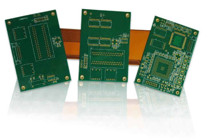
A board that is large and thick behaves differently from a small one at every stage of assembly. It carries more thermal mass, it distorts more readily under heat, and the accuracy of placement has to be maintained over a longer distance. Boards of this class, which are common in high-performance computing and in equipment where a single assembly carries a great deal of function, are therefore a separate manufacturing problem.
The two difficulties that dominate are warpage and the maintenance of placement accuracy across the whole panel. Both are manageable, and both are managed before the run rather than during it.
Why a Thick Board Distorts
Every material in the assembly expands when heated, and the layers of a multilayer board do not all expand by the same amount or in the same direction. Copper expands differently from the resin and the reinforcement, and the distribution of copper differs between a signal layer and a plane.
Where the board is thin, the structure flexes and the internal stresses relieve themselves. Where it is thick and stiff, the same stresses produce a bow or a twist, and the movement continues as the board cools. The result is a board that is flat at room temperature and not flat when the joints were formed.
For an area-array package, that is a direct risk. The balls are all supposed to contact their pads simultaneously, and a board that moves during the process leaves some joints formed and others not. The defect is invisible from the outside and appears as an intermittent connection later.
Support and the Reflow Profile
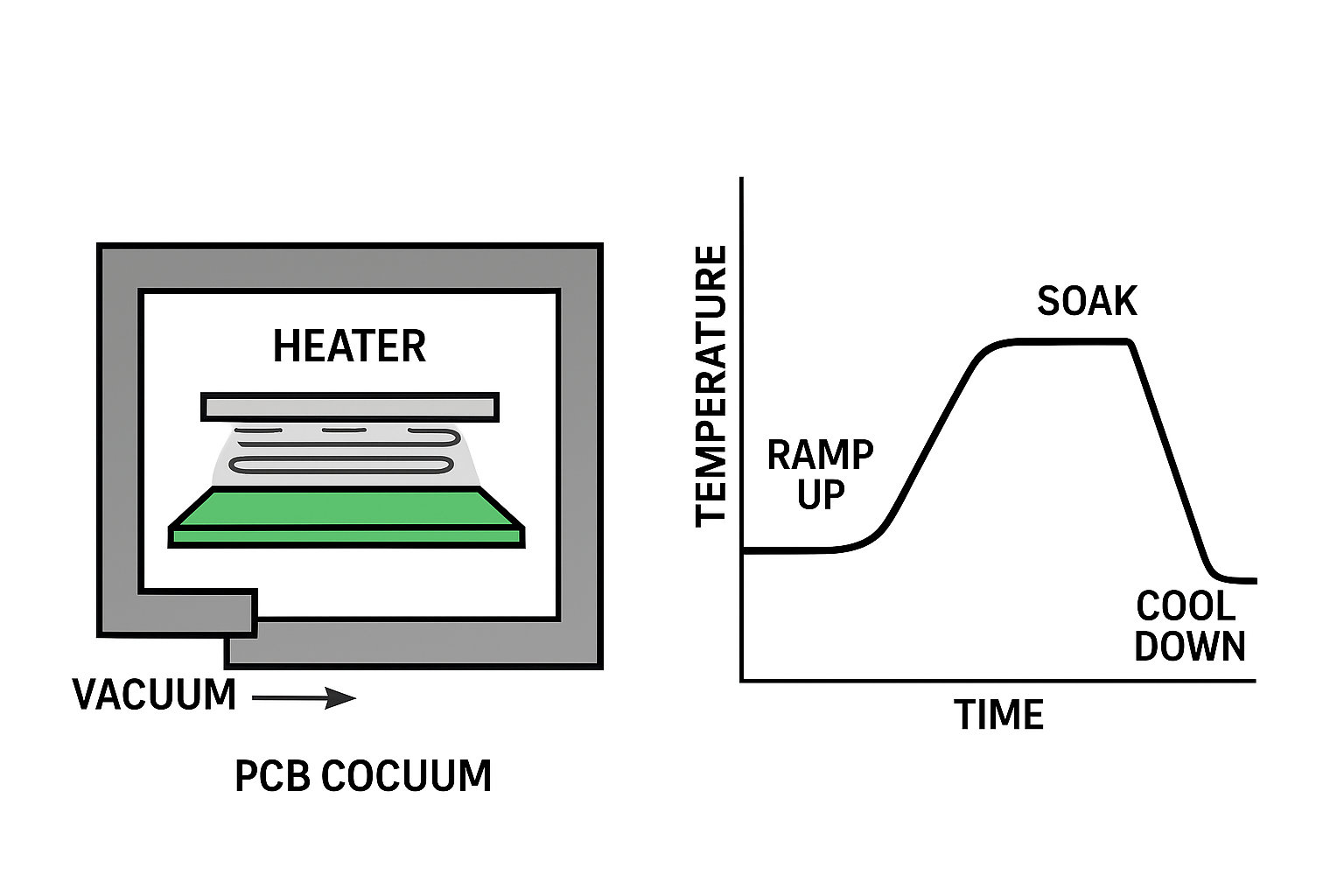
Support is the first control. A large thick board is carried through the oven on a fixture rather than on the conveyor belts alone, so that the middle of the board does not sag under its own weight at temperature. The fixture has to tolerate the same temperature without itself distorting, and it has to allow the heated air to reach the underside uniformly.
The profile is the second control, and it is set for the assembly rather than for the solder. A slower ramp reduces the temperature difference between the surface and the interior of a thick board, and a longer soak allows the whole structure to reach a uniform temperature before the joints form. Both cost time and both reduce the amount of movement.
Measuring the profile is not optional on a board of this class. Thermocouples placed at the corners and the centre of the panel show whether the assembly is being heated evenly, and on a large board the difference between those positions is often greater than the whole process window.
The Placement Accuracy Problem Over Distance
Placement accuracy is quoted for a machine, and on a large panel it has to be maintained across a much longer travel. Small angular errors that are negligible over a short distance become visible offsets at the far corner, and the fiducial arrangement is what allows the machine to correct for them.
Where the fiducials are sparse or placed so that rotation cannot be measured, a board that is slightly rotated cannot be corrected, and the error appears as a uniform displacement at one end of the panel. Adding fiducials at the corners of the panel, and keeping the area around them clear of anything the vision system might mistake for a mark, is a small design change with a large effect.
On this class of board the placement programme also runs for longer, and the stability of the machine over that time becomes a factor. A drift that is invisible over a small panel can accumulate across a large one.
Stencil, Paste and the Tall Components
A large board puts demands on the printing stage as well. The stencil has to span the whole panel with consistent tension, and the board has to be supported so that it does not flex under the squeegee. Where the panel sags in the middle, the deposits at the centre will differ in volume from those at the edges.
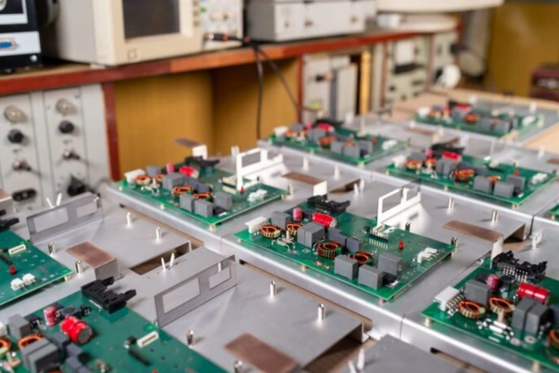
The profile of the assembly matters too. Components of very different heights have to pass through the oven without touching anything, and a heavy connector or transformer adds its own thermal mass and mechanical load. Both are reasons to review the assembly against the equipment before the order rather than after.
Where the board also carries inserted parts, the sequence continues after reflow and the same support and thermal questions reappear in the soldering operation, which is one reason to plan the whole sequence at the outset.
Reliability and the Environment
Boards of this class are usually intended for continuous operation, which changes the requirement from working on the bench to working for years. A joint that is marginally formed will be stressed by every thermal cycle, and the failure appears in service rather than in the factory.
That is the argument for a defined thermal or load test on the finished assembly, and for measuring something during it. A unit that is run at temperature with its behaviour recorded produces a number that can be compared between batches; a unit that is only switched on produces an impression.
Where the product will be used in a demanding environment, the same reasoning applies to the coating and the mechanical fixing: both protect joints that would otherwise be exposed to moisture and to movement.
Inspecting the Result
Measuring warpage is straightforward and worth doing on a board of this class: the panel is placed on a flat surface and the deviation from flatness is measured before and after the reflow cycle. The before measurement is the baseline, and the after measurement is the effect of the process.
That pair of numbers is what allows the process to be adjusted with evidence rather than by intuition. Where the movement appears during the ramp, the profile is the place to look; where the board is already bowed before it enters the oven, the question belongs to the stack-up or to the handling of the panels.
For joints that cannot be seen, the same logic applies. A defined check on the first article and on a sample produces a record of the process, while an assurance that the joints are inspected produces nothing that can be compared later. The support fixture belongs to the same discussion, since it is the item that limits how much the board can move at all.
The data package is the usual one, with attention to the details that matter on a large board: the panel arrangement, the fiducial positions, the identification of the devices that cannot be seen after reflow, the height and mass of any heavy component, and the environment in which the product will operate.
The purpose of the board is worth stating as well, since it determines how much verification is appropriate. A prototype that will be tested on a bench and a unit that will run continuously in an installation are the same drawing and different requirements. The operations concerned are SMT assembly, with verification through PCBA testing and the controls that keep a batch repeatable under quality management.
FAQ
Why does a thick board warp during reflow? Because the layers expand by different amounts and a stiff structure cannot relieve the resulting stress by flexing as a thin board does.
What reduces the risk? Support under the board, a slower ramp and a longer soak to even out the temperature, and a profile measured on the actual assembly.
Why do fiducials matter more on a large panel? Because the machine corrects its position from them, and an uncorrected angular error becomes a visible offset at the far end of a long panel.


2 Comments
PCB Warpage: Causes and Controls
[…] At the extreme, this is a matter of layer count and thickness together. Very thick, high layer count boards are rigid but are pressed with high forces and accumulate large internal stresses; controlling their flatness is described in the note on warpage control for large thick boards. […]
Balanced Stackup and Layer Count
[…] The same logic applies at the other end of the scale, where very thick stacks create their own warpage problems through the same mechanism of unbalanced construction and uneven copper. The controls used there are described in this discussion of warpage control on large thick boards. […]