Automotive ECU PCB Design: Mixed-Signal Layout and Reliability
Walk into a modern vehicle and you are surrounded by dozens of hidden computers: airbag controllers, all-wheel-drive modules, GPS navigation, ADAS processors, infotainment, cameras, lidar and a cloud of small sensor nodes. Vehicle programmes routinely carry hundreds of electronic control units, and almost every one of them is a board. Designing automotive ECU hardware is therefore less about a single clever circuit and more about making hundreds of boards behave predictably for a decade in an environment that punishes everything.
What Makes Vehicle Electronics Different
Board design for consumer products optimises cost, size and time to market. Vehicle design adds constraints that rarely appear elsewhere, and they interact.
The environment is the first constraint. A module under the bonnet sees temperatures that swing from a cold soak well below freezing to soak heat that bakes the laminate; a module in the cabin sees vibration, humidity and, eventually, condensation. Electronics that sit inside a door or behind a bumper must survive there for a service life measured in ten years or more.
Cost and weight are the second constraint. Every gram and every gram of copper matters when a platform builds hundreds of thousands of units, so material substitutions are made carefully rather than generously. At the same time, the mechanical package can be brutally small. Many vehicle boards use very little area and high layer counts because the space available behind a dashboard or inside a mirror housing is not negotiable.
Reliability is the third. A phone that reboots is an annoyance. A brake controller that drops a frame is a recall. This is why simulation, derating and test coverage dominate the schedule.
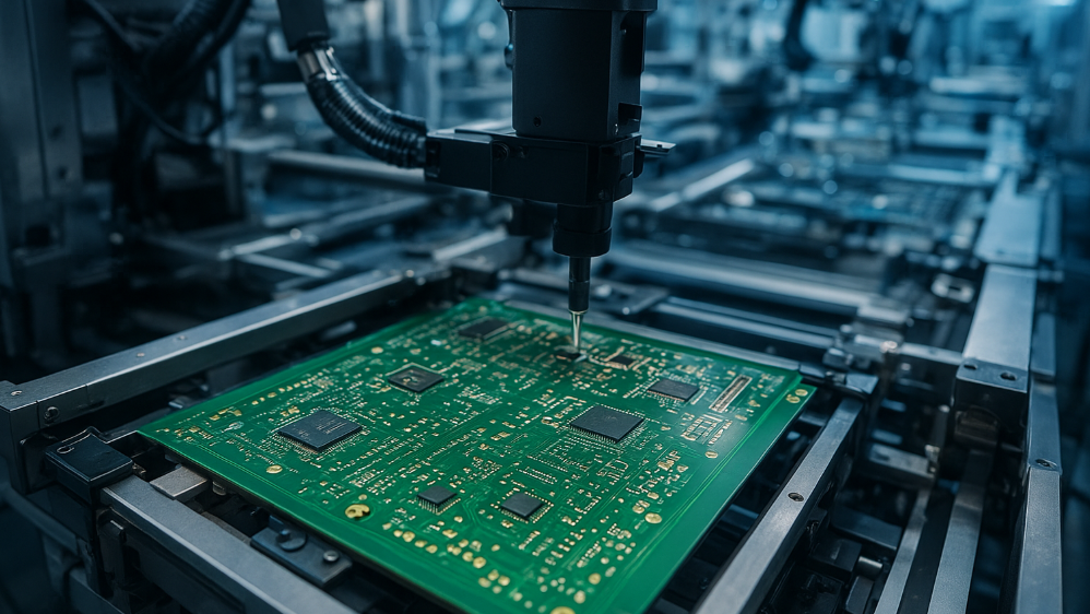
The practical consequence is that the fabrication partner matters earlier than usual. Boards that must fit tight mechanical envelopes at high layer counts, in low volumes during development and high volumes in production, are far easier to develop with a manufacturer who can build both.

Design Requirements at System Level
Several pressures shape the architecture before layout begins.
Wiring harnesses used to carry signals mechanically. Increasingly the harness carries power and data, and the function is distributed between sensors, actuators and controllers in what is loosely called drive-by-wire. This reduces harness mass and moves complexity onto the boards.
Power distribution has followed the same path. Higher voltage rails and hybrid drive systems push designers toward dense power electronics that must switch fast, dissipate real heat and stay within emissions limits.
Mixed-signal content keeps growing. Oxygen sensors, tyre pressure monitors, current shunts and position sensors are analogue; the loops that close around them are digital. A single module may contain precision analogue front ends, switching regulators, a microcontroller and a communication transceiver, all sharing one ground system.
Because so much of the behaviour depends on tolerances, temperature and ageing, simulation carries more weight than bench iteration. Virtual prototyping of hardware and software together, plus software verification before hardware exists, is standard practice in programmes that cannot afford late changes.
Mixed-Signal Layout Strategy
Mixed-signal behaviour is decided by return paths, not by component choice. Treat the return current as carefully as the signal itself.
Keep analogue and digital sections physically separated, run their return paths on separate conductors, and bring them together at a single controlled point rather than over a broad plane. Keep loop areas small: the smaller the loop, the less flux it couples and the less it radiates. Do not place sensitive analogue circuitry in the region between connectors, where return currents from other nets flow.
Control the transition times of digital edges. A faster edge is not automatically better; it broadens the spectrum that must be contained. Finally, watch the integrity of the return plane. A slot or a via field that cuts across a return path turns a well-behaved trace into a loop antenna, and the symptom appears as noise in an unrelated channel. Background on how power and return structures interact is covered in this discussion of power and ground planning for mixed-signal boards.
Standards: Who Qualifies the Supplier
The automotive quality system has its own history. QS9000 was introduced in the 1990s by the large vehicle manufacturers to impose a common quality management system on suppliers. In the 2000s it was replaced by ISO/TS16949, which consolidated the requirements into one scheme covering defect prevention, reduction of variation and waste reduction across the supply chain.
For a board shop, ISO/TS16949 certification is the entry ticket rather than a differentiator: many manufacturers must hold it before they can quote on vehicle programmes at all. For a design team, the practical meaning is documentation. Process capability evidence, change control and traceability are expected on every part number, not only on the difficult ones.
RFI and EMI
Electromagnetic interference, often called radio frequency interference, deserves attention from the first schematic revision. In a vehicle, both the source and the victim are unusual: motors, relays, ignition systems and switching converters generate broadband noise, while the wiring harness acts as an antenna that can deliver that noise to modules far from its origin. Even non-metallic body panels play a part, since plastic bumper covers and trims neither shield nor ground effectively.
The countermeasures are conventional and must be planned rather than added: shielding cans and grounded enclosures over sensitive sections, short and low-impedance ground connections, filtering at connector pins, and controlled edge rates. The goal is not only to protect the module but to stop the module from becoming a transmitter through its own harness.
CAN bus Layout
A controller area network bus runs at modest rates by modern standards, so its routing does not require the length matching or impedance discipline of a multi-gigabit link. That does not make it trivial.
Keep fast falling and rising nodes, switching regulators and other switching nodes at a safe distance from the data pair so that inductive coupling cannot inject into it. Terminate and route the pair as a pair, with short stubs and direct paths; in an asynchronous hierarchy a slightly uneven length is tolerable, but every stub adds a discontinuity.
Crosstalk is the main threat in practice. When energy from an adjacent conductor couples into the communication bus, signal integrity degrades across the whole network, and bundled harnesses with many pairs running shoulder to shoulder make it worse. Twisted pair is the simplest effective remedy. Automotive Ethernet, used where bandwidth demands it, brings materially better crosstalk immunity and signal integrity, and it also changes the layout constraints entirely.
Fabrication Choices
Vehicle boards push several process capabilities at once.
Radar and collision-avoidance functions communicate at microwave frequencies, so substrate loss becomes a design parameter. Low-loss laminates such as PTFE-based materials are used, and they bring their own fabrication requirements, including specialised via drilling and controlled processing.
Heat is the second driver. Dense electronics plus high-current power stages plus electric drivetrain systems mean real thermal load, and thick copper and heavier metal cores are used to move that heat and carry current without excessive temperature rise.
Density is the third. Because a module now provides navigation, media, connectivity and camera processing inside a small housing, high density interconnect is common, with microvias, sequential lamination and fine-line plating as normal parts of the flow. A manufacturer experienced in automotive work will design the stackup around these constraints from the start; this overview of boards for vehicle electronics covers the base materials and structures involved.
Substrates Beyond FR-4
Standard FR-4 has limits, and vehicle electronics regularly cross them.
Ceramic substrates offer high thermal conductivity and a coefficient of thermal expansion that pairs well with bare die, which is why they appear in high-power and high-temperature vehicle circuits where FR-4 would degrade. Beyond thermal performance, ceramic withstands high vibration and corrosive environments well and suits dense power conversion.
Flexible circuits and rigid-flex constructions are used where vibration is constant. The boards are expected to flex repeatedly without cracking, which depends on the copper type and the stackup, with annealed copper chosen for flex layers. Rigid-flex also removes connectors and harnesses, which is attractive for both reliability and mass.
Reliability Testing
Testing is where the design is proved, and for vehicle boards the suite is broad because the operating environment is broad — a chassis module, a transmission module and an engine-bay module each have their own temperature extremes.
Thermal shock. Boards are immersed in solder at 260 degrees Celsius for ten seconds, three times, then inspected for delamination, blistering and cracks. The test verifies that the laminate and plating survive assembly and rework heat.
Temperature, humidity and bias. Because modules operate in wet and humid conditions, humidity testing matters, and conductive anodic filament growth is a key failure mode. CAF is evaluated between adjacent vias, between a via and a trace, and between adjacent traces, since it grows along the fibre-resin interface under bias and moisture.
Thermal cycling. Cycled between the extremes defined for the mounting location, the board and its solder joints are checked for fatigue damage. This is the test that most often exposes a stackup that was chosen for cost rather than for expansion matching.
These tests are also the reason test planning should start at concept stage. The reliability programme for a vehicle assembly is worth mapping out early, as outlined in this note on automotive PCBA test and reliability planning.
Simulation as a Design Tool
Because a vehicle module cannot be prototyped into existence, simulation software carries a large share of the verification load. A single environment used for control-unit simulation lets designers evaluate a module at whatever level of abstraction is useful, find performance problems before they reach hardware, carry out risk assessment and catch integration issues while changes are still cheap.
Combined with mixed-signal control loop modelling and drive-by-wire designs, this allows system-level analysis of the whole function rather than of one board. The result is a shorter design cycle and a control unit that arrives closer to the quality and reliability targets the programme requires, with fewer late changes and less rework at the end.
FAQ
Why does an automotive board need low-loss laminate? Because radar and collision-avoidance functions operate at microwave frequencies, where dielectric loss in ordinary FR-4 attenuates the signal. PTFE-based materials reduce that loss, at the cost of additional drilling and process requirements.
Is length matching required for a CAN bus? Not in the strict sense used for multi-gigabit links. Short, direct routes matter more; the priority is separating switching nodes from the data pair and avoiding stubs and crosstalk rather than matching lengths to a tolerance.
What does the 260 degree Celsius thermal shock test prove? It proves the board survives assembly and rework heat. After three ten-second immersions in molten solder, the panel is inspected for delamination, blistering and cracks, which are the failure modes that would otherwise appear in the field.