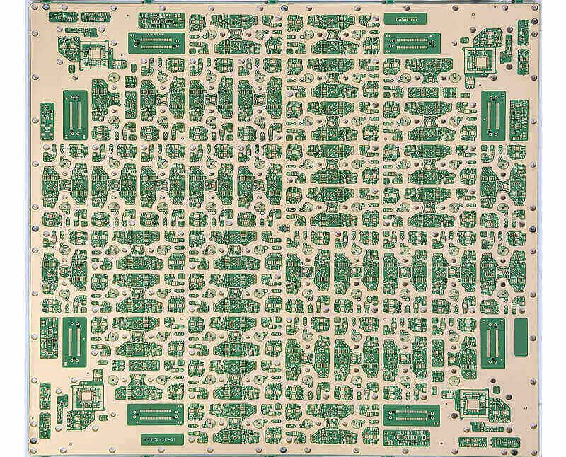
Board Bring-Up: Debugging a Newly Assembled PCB
A newly assembled board is a hypothesis, not a product. Debugging it is straightforward when the board is small and miserable when it is large and densely populated, because there are too many possible faults to test one at a time. A disciplined sequence turns that search into a procedure: the goal of board bring-up is to reduce the number of unknowns before each power-up, so that whatever happens can only have a few explanations.
Before Applying Power
The first pass requires no instruments.
Look the board over for obvious problems: cracks, contamination, signs of overheating and — most importantly — any visible short or open. On a new assembly, solder bridges and unsoldered pins are more common than design errors, and they are found by inspection rather than by reasoning.
Then measure the resistance between the supply rail and ground. It should be high. A low reading means current will flow the moment power is applied, and the components on that rail will not survive the experience. This single measurement prevents a large proportion of the damage that inexperienced bring-up causes.
Populate in Stages
If the board contains modules that are functionally independent and there is any doubt about whether they work, do not fit everything at once. Populate incrementally, so that a fault can be attributed to the section just added. Small circuits can usually be assembled complete; larger ones cannot.
The sensible order starts with power. Fit the supply section, apply power, and confirm the output voltage before anything downstream is present to be damaged by it.
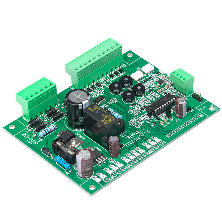
First Power-Up
Use a supply that can limit current. An adjustable supply with a current limit is the single most useful instrument for this work, because it converts a mistake into a current reading rather than a destroyed component.
Set the current limit to a value you are prepared to see drawn, then bring the voltage up gradually rather than switching it on. While you raise it, watch three things: input current, input voltage and output voltage.
If the current stays under the limit and the output reaches its expected value, the power section is working. If the limit trips, or the current is higher than the design predicts, remove power immediately and find the cause before repeating the exercise. Then repeat the sequence — gradual ramp, monitored current — until the rail behaves.
A fuse is worth fitting even when you are confident. Confidence is not a measurement.
Adding the Rest of the Board
Once the supply is verified, fit the remaining modules one at a time, applying power and checking after each addition, using the same gradual ramp with the current limit in place. This costs time and saves far more of it: when a new section causes the current to jump, you know precisely where to look, and you know the problem was introduced by that section or by its interaction with what was already fitted.
Finding the Fault: Measure Voltages
When something is wrong, voltage measurement is the fastest first move.
Check the supply pins of each device first, then the reference voltages, then the operating points of the circuit. The values tell you where the signal path stops behaving.
Semiconductor junctions give useful reference figures. A conducting silicon transistor typically shows around 0.7 volts across its base-emitter junction and 0.3 volts or less across collector-emitter. A base-emitter voltage well above 0.7 volts — excluding devices that are designed that way, such as Darlington pairs — suggests the junction is open. Readings like these convert a vague symptom into a specific suspect.
Finding the Fault by Signal Injection
The second technique follows the signal path from the input onward.
Apply a signal at the input and measure the waveform at each successive point until it stops looking correct. The stage where it changes is the stage to examine.
A simpler version is often enough. Touching a probe or a pair of tweezers to the input of a stage will inject enough noise to produce a visible or audible response in an amplifier. Working stage by stage, a stage that produces no response while the following stage does is the faulty one. This is common practice in audio and video circuits.
Two cautions apply. Circuits with a live chassis or with high voltage must not be touched this way, for obvious reasons. And the technique proves a stage responds, not that it performs to specification — it locates a fault rather than validating a design.

Finding the Fault: Use Your Senses
Four senses are legitimate diagnostic instruments, and experienced engineers use them before the oscilloscope comes out.
Sight finds mechanical damage: cracked, discoloured or deformed components, and joints that look different from their neighbours.
Hearing finds audible symptoms: something that should be silent making noise, or something that should be making noise staying quiet, or noise at the wrong pitch.
Smell finds failing components. Burnt resin, overheated insulation and electrolytic capacitor electrolyte all have distinct odours, and recognising them narrows the search immediately.
Touch finds thermal problems. A power device that runs cool is probably not running at all; a device that should be cool and is hot, or one that is far hotter than it should be, is a fault. Around seventy degrees Celsius is a useful practical limit for components such as power transistors and regulators, and a rough calibration is available to anyone: if you can hold your finger on it for more than about three seconds, it is probably below that temperature. Approach hot components cautiously rather than pressing on them.
When the Board Is the Problem
Not every fault found during bring-up is a design fault. Assembly defects — insufficient solder, cracked joints, a bridged pin — account for a large share of failures on a new board, and they are checked first because they are cheaper to find. The controls that prevent them, and the checks that detect them, are described in this discussion of reflow quality and assembly stability and in this overview of PCB inspection after fabrication.
Where a fault does trace back to the design, the useful step is to record it against the layout. Bridging that survives assembly often indicates a pad spacing that is too tight, and opens that appear only under thermal cycling often indicate a via or annular ring that is marginal. The measures that prevent the second category are covered in this note on short circuit prevention.
The purpose of bring-up is not to prove that the design works. It is to find the faults quickly, in an order that keeps each one attributable, and to leave behind a record that makes the next revision better than this one.
FAQ
Why use a current-limited supply? Because it converts a fault into a measurement. Without a limit, a short circuit or a reversed component draws whatever the supply can deliver and destroys parts that would otherwise have been salvageable.
Why populate the board in stages? To keep faults attributable. If every part is fitted before the first power-up, a wrong current reading could come from any of them, and isolating the cause means removing and refitting components.
Is the touch test safe? Only with care and only on low-voltage circuits. Component temperatures can burn skin, and high-voltage or live-chassis circuits must be treated with proper precautions rather than with fingers.