Panel and Fiducial Design Rules for Automated SMT Assembly
An automated surface mount line can place tens of thousands of parts an hour, but only if the board presents itself to the machine in a form the machine can handle. Panel geometry, edge conditions, fiducial placement and tooling holes are not housekeeping details; they decide whether the printer and the placer can find the board at all. Panel and fiducial design is therefore the first thing to fix in a layout that will be assembled automatically.
What an Automated Line Needs From the Layout
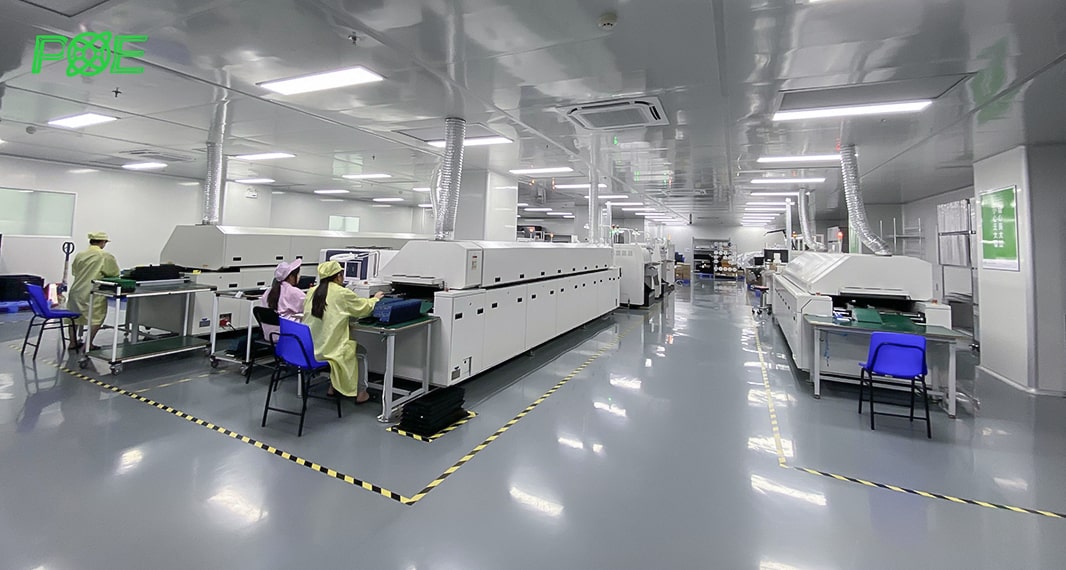
A standard line runs a loader, a paste printer, one or more placement machines, a reflow oven and an unloader, with the board travelling along rails between them. Every station references the same physical features: the edges that the conveyor grips, the tooling holes that set the panel position, and the fiducial marks that the vision system uses to correct for panel offset and stretch.
If any of those features is missing, ambiguous or obstructed, the machine either stops or places by dead reckoning, and the resulting offset shows up as a placement defect that no amount of reflow tuning will fix.
Process rails are the usual answer when the finished outline cannot provide what the machine needs. A rail is a strip of laminate added to the panel that carries the tooling holes and supplies the grip surface, and it is broken off with the rest of the panel at the end. Typical rail width is 5 to 10 mm, and a rail is needed on both edges that the conveyor touches, with enough material at the ends for the loader and unloader to push against.
Board Outline and the Clamp Edge
The conveyor grips the panel along two opposite edges, and those edges have to be straight, parallel and free of interruption. A rectangular outline gives a flat, uniform grip. Where a corner has to be rounded or chamfered for the enclosure, the chamfer is kept away from the grip region, or a process rail is added to the panel so that the conveyor never touches the finished board.
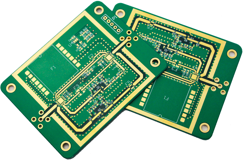
The clamp edge must also be free of components. Tall parts sitting under the conveyor rail will be crushed or pushed out of position as the panel enters the machine, and parts placed near the board edge may interfere with the rail itself. The usual arrangement is to reserve a strip of 3 to 5 mm along the gripped edges for tooling only, and to orient any component that sits near the outline parallel to the direction of travel. The mechanical rules for outlines, slots and mounting features are described in the notes on board outline and mounting design.
Board Size, Thickness and Aspect Ratio
Machine envelopes define the limits. Most placement equipment handles panels from roughly 50 mm square up to about 330 by 250 mm, with some machines accepting 410 by 360 mm. A design smaller than the minimum is not rejected; it is panelised, so the effective board presented to the line falls inside the window.
Thickness interacts with size. A thin board in a large panel sags in the printer and warps in the oven, so the board aspect ratio of length to width is usually kept near 3 to 2 or 4 to 3, and a thin laminate is kept to a smaller panel than a thick one. Where the design is inherently long and narrow, stiffeners or a carrier are used rather than running the risk of distortion through reflow.
Tooling Holes and Positioning
Positioning can be done with tooling holes, with edge stops, or with fiducial recognition. Fiducial recognition is the most common because it needs no mechanical contact and can correct for the small scale changes a panel picks up during lamination. Tooling holes are still used where the panel has to be located mechanically, such as in a router or a test fixture, and they should be sized and positioned consistently so that one set of tooling serves the whole line. How the parts themselves are ordered and positioned is covered in the notes on placement order and pad positioning.
Hole tolerance is what makes tooling work. A panel located by two holes on one edge and a slot on the other repeats within a few tens of microns, while a panel located by four round holes fights its own tolerance stack and binds on the pins. Where a test fixture or a router uses the same tooling, the positions should be taken from one drawing rather than re-derived by each supplier.
Fiducial Marks
A fiducial mark is the reference the vision system locks onto. A solid circle is the preferred shape because it gives the most consistent centroid under different lighting, with square and diamond marks used when the board surface provides no contrast. The mark is normally 1 mm in diameter, within a permitted range of about 0.5 to 3 mm depending on the machine.
<img src="https://www.gopcba.com/wp-content/uploads/2026/08/1-3-jpg-1.webp" alt="V-score grooves between boards in an SMT panel” />
The surface of the mark has to be as flat and as uniform as a pad, which means the same finish and the same plating as the surrounding copper, with no solder mask or legend over it. Around each mark there must be a clear area with no copper, no mask and no silkscreen, because a printed line passing near a fiducial softens the edge that the camera is trying to measure and provokes repeated recognition alarms. Three marks, placed asymmetrically, allow the machine to correct rotation as well as translation and are standard on any panel that carries fine pitch devices.
Panelisation and V-Score
Small boards are combined into a panel to raise throughput and to keep the panel inside the machine envelope. The connection between the individual boards is either a set of stamp holes or a V-score groove cut along the separation line. V-scoring is fast and leaves a clean edge, but the depth is critical: the remaining material should be about one quarter to one third of the board thickness.
Cutting deeper weakens the web, and a panel that has been over-scored can separate in the reflow oven, drop onto the conveyor and jam the line or scorch. Cutting shallower leaves a ridge that has to be removed later and loads the edge of the board when it is snapped apart. The groove position should also avoid routing and planes, so the layout has to know the scoring lines before the copper is drawn.
Tab routing with perforated bridges is the alternative where a clean edge matters or where the outline is irregular. The bridges are sized so that they can be separated by hand or with a cutting tool without transferring stress into a solder joint, and the tabs are placed away from heavy components. Whichever method is chosen, the separation direction should run parallel to the long axis of the parts near the edge, which is a layout decision rather than a fabrication one.
Data for the Assembly House
The data package for an automated build should state the panel dimensions, the rail width, the fiducial type and position, the tooling hole coordinates and the depanelisation method. Assembly drawings that show only the single board and leave the panel to the supplier are a frequent source of tooling delay, because the supplier has to invent the rail and then ask for approval. Supplying the panel drawing up front shortens the first article cycle and removes a whole class of avoidable questions. The wider set of layout decisions that affect production is set out in PCB layout decisions that affect production.
It is worth stating the machine envelope the panel was designed for. A panel that fits the printer but not the reflow oven, or that exceeds the width of the placement rails, is normally discovered at the worst possible moment. Supplying the intended line configuration removes that risk for the cost of one note on the drawing.
FAQ
How many fiducial marks should a panel have? At least three, placed asymmetrically. Two allow translation and rotation only in theory; three give the vision system a robust fit and detect panel stretch.
Can a board edge with a cut-out be used as a clamp edge? Only if the cut-out is filled or bridged with a process rail. The conveyor needs a continuous straight surface to grip.
What happens if silkscreen is printed close to a fiducial? Recognition becomes unreliable and the machine raises repeated alignment alarms, which slows the line and can force manual intervention.