Aerospace PCB: Design and Reliability Requirements
An aerospace PCB is not simply a well made circuit board. It is a board that has been designed, qualified and documented to survive an environment that punishes every weak point at once: wide temperature swings, sustained vibration, low air pressure, humidity and, in some cases, radiation. The electrical function may be modest, but the evidence that the function will still be there after ten years of service is what separates an aerospace design from a consumer one.
What Changes Compared with Commercial Work
The differences appear at every stage. Materials are selected for their behaviour across the full temperature range rather than at room temperature. Every solder joint is evaluated for thermal fatigue. Components are derated far beyond commercial practice, so a part rated for a hundred degrees may be used only to seventy. Documentation is complete enough that a board can be traced back to the panel, the laminate lot and the operator who inspected it.
The standard that governs much of this is IPC Class 3, which sets requirements for plated hole quality, annular ring, inspection criteria and acceptability of rework. A board built to Class 3 is inspected more strictly at every step, and the resulting yield is lower and the cost higher. That cost is not an inefficiency; it is the price of knowing that a joint which looked marginal has been removed from the population rather than shipped.
Material and Stack-Up Choices
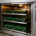
Polyimide laminates are common because they tolerate the high end of the temperature range without degrading and because they can be made thin without losing mechanical integrity. The trade-off is that polyimide absorbs more moisture than FR-4, which makes the bake before assembly more critical, and it is more expensive and harder to process.
Outgassing is the second material consideration. In a vacuum, any absorbed or residual volatiles leave the board and can condense on optical surfaces, sensors or thermal control hardware. Materials are therefore selected for low outgassing, and the laminate, the solder mask, the conformal coating and the adhesives are all assessed rather than just the base material. A stack-up that is symmetric is also preferred, because an unbalanced construction will bow when it goes through the thermal excursions of assembly and of service, and a bowed board stresses every joint on it. Our layer assignment notes describe how the arrangement is planned.
Thermal Cycling and Fatigue
Thermal cycling is the dominant failure mechanism. The laminate, the copper, the plated barrel and the solder all expand by different amounts as the temperature changes, and each cycle consumes a small part of the joint’s fatigue life. A plated through hole in a thick board is the hardest case, because the barrel must stretch to accommodate the expansion of the board in the z direction, and the copper will eventually crack at the knee where the barrel meets the pad.
Design measures reduce the strain. Thin boards flex more easily, so reducing the overall thickness helps. A high aspect ratio, meaning a small hole in a thick board, concentrates the strain and should be avoided. Where a plated hole must exist in a demanding location, filled and capped vias and a thicker copper plating both extend life. Our component tolerance and reliability notes describe how the fatigue life is estimated.
Vibration, Shock and Mechanical Fixation
Vibration is the second environment that shapes the design. A board mounted only at its corners will flex at its centre, and component leads and solder joints at the antinodes of that motion fatigue quickly. The standard remedies are to add mounting points, to increase the stiffness of the board, or to place the heavy components near the mounting points rather than in the middle.
Large and heavy components deserve individual attention. A connector or a transformer should be mechanically restrained by its own fixing rather than relying on its solder joints, and components that stand above the board should be supported or potted. Conformal coating over the finished assembly adds protection against moisture and contamination and provides a small amount of mechanical damping, though it must be selected so that it does not trap contaminants or stress delicate parts.
Traceability, Documentation and Inspection
Documentation is part of the deliverable. The fabrication drawing specifies the laminate, the copper weight, the plating thickness, the surface finish and the acceptance standard, and it records the panel and lot numbers so a failure in service can be traced to the material that produced it. This is the practice that makes an escape visible rather than mysterious.
Inspection follows the same logic. Coupons on the panel are cross sectioned and measured for plating thickness, and the results are recorded rather than simply pass or fail. Microsection is performed periodically through the production run, not only at the start, because a plating bath drifts. X-ray inspection verifies the joints that cannot be seen, and electrical test verifies every net rather than a sample.

Power, Grounding and Signal Integrity
Aerospace systems combine sensitive analogue and radio frequency circuitry with high current actuators and switching supplies on the same platform, and often on the same board. Continuous ground planes, careful segregation of the noisy and quiet sections, and filtering at every interface are the measures that keep them compatible. Where the board drives a motor or an actuator, the return current is kept out of the signal reference plane by routing it on its own path rather than letting it choose.
Redundancy is frequently a requirement rather than an option. Two independent channels may be laid out side by side so that a single failure cannot disable both, which means the routing deliberately avoids sharing a via, a plane or a connector pin between the channels. The layout has to respect that separation physically, because a shared path is a single point of failure regardless of how the schematic is drawn.
Test and Qualification
Qualification is where the design is proved. Thermal cycling between the specified extremes, vibration at the specified profile, humidity and, where relevant, thermal vacuum testing are performed on production-representative hardware. Electrical performance is measured before, during and after, because the failures that matter are frequently intermittent and appear only at one temperature or one vibration level.
The results feed back into the design. A joint that fails after two hundred cycles does not need a new material, it needs a different geometry; a component that drifts at the cold extreme may need a different part or a compensation network. Our design release checklist places these reviews in a sequence that catches the cheap problems before the expensive test campaign begins.
FAQ
Why is an aerospace PCB so much more expensive? Lower yield, stricter inspection, documented traceability, higher-grade materials and the qualification testing that follows. Much of the cost is in the evidence rather than in the materials themselves.
Is FR-4 ever used in aerospace? Yes, in benign locations such as equipment inside a pressurised and temperature-controlled bay. Where the board sees the full thermal range or the vacuum of space, polyimide and low outgassing materials are used instead.
What is the most common cause of aerospace board failure? Thermal cycling fatigue at plated through holes and solder joints, often at the knee of a barrel or on a large component that was not mechanically restrained.