Through-Hole PCB Assembly: Where It Still Wins
Surface mount technology dominates modern electronics, and yet a large share of critical products still uses pins that pass through the board. Automotive ignition circuits, aerospace avionics, industrial controllers, and power supplies rely on a through-hole PCB because the joint it produces is mechanically strong, thermally tolerant, and easy to inspect. This is a technology that survived not by inertia but by solving problems that surface mount does not.
What a through-hole board is
A through-hole PCB uses drilled holes and leaded components: the pins of each part are inserted through the board and soldered on the far side, forming both the electrical connection and the mechanical attachment. The holes may be plated, which makes them part of the electrical network, or unplated where they serve only a mechanical purpose.
The construction suits axial and radial leaded parts, produces a high-strength solder joint, and works with either a double-sided or a multilayer board. Those features are unremarkable individually, and together they explain why the technology remains in the tool kit.
A short history
Through-hole assembly dates from the 1950s and was the standard method of electronic manufacture for decades, initially with every component inserted by hand and soldered on the reverse side. Automatic insertion equipment later raised the throughput, and the arrival of surface mount in the 1980s shifted the mainstream towards smaller components and reflow soldering.
What did not change is the demand for reliability. The applications that cannot tolerate a field failure kept using through-hole parts, and they still do, because the failure modes of a through-hole joint are better understood, easier to inspect, and slower to develop than those of a small surface mount joint under thermal cycling.
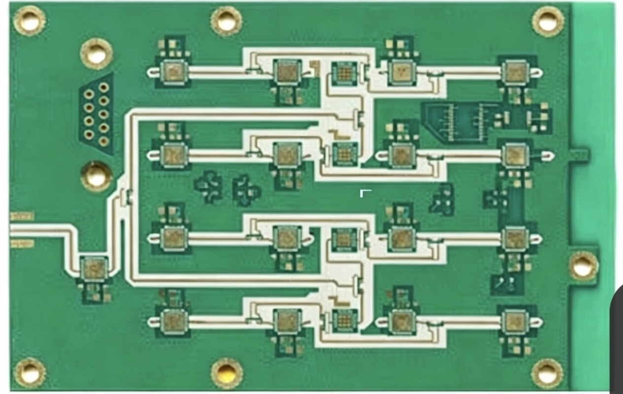
A through-hole joint is visible from the solder side and reaches through the board. That combination is why it is still specified where inspection has to be conclusive.
How the assembly is done
Manual insertion covers prototypes, small batches, and educational work, where flexibility matters more than throughput. Automatic insertion serves volume production, where components are placed by machine and the board then passes over a wave soldering process that solders every joint in one pass.
Mixed-technology boards use selective soldering instead, which applies heat and solder only to the through-hole joints while leaving the surface mount assembly untouched. The choice between wave and selective soldering depends on whether the board carries surface mount parts on the solder side, since those must be protected from the solder wave.
Common through-hole components
The parts that remain through-hole are the ones with a physical reason to be: axial and radial resistors, capacitors, diodes, transistors, connectors and pin headers, and transformers. They share characteristics that surface mount parts handle less well, including high current, mechanical load, vibration, and elevated temperature.
Connectors are a useful illustration. A connector has to survive cable forces as well as electrical requirements, and a through-hole solder joint distributes that load into the board rather than concentrating it at a surface pad.
Why it is still specified
Mechanical strength is the primary reason. A lead that passes through the board and is soldered on the far side resists pull, shear, and vibration far better than a joint that sits only on the surface, which is why connectors, transformers, and heavy parts are still mounted this way.
Prototyping is the second reason. A through-hole board is easy to populate by hand, easy to modify, and easy to rework, which makes it the natural choice for development work. Thermal tolerance is the third: a large leaded component can dissipate heat into the board and the joint tolerates the temperatures involved, which suits power circuitry. Joint reliability in military and automotive applications follows from all three.
Limits
The disadvantages are equally clear. Through-hole components occupy more board area, which conflicts with compact product design. Insertion and soldering are slower than a surface mount process, and the assembly cost is correspondingly higher.
Those penalties are acceptable where reliability dominates and unacceptable where size and weight do, which is why the two technologies coexist rather than compete.
Through-hole compared with surface mount
Component size is the most visible difference: surface mount parts are much smaller. Mechanical strength favours through-hole, and so does heat tolerance, while cost and automation favour surface mount. The typical application differs too, with through-hole dominating high-reliability industrial, automotive, and aerospace work, and surface mount dominating density-driven products.
The useful conclusion is that the choice follows the requirement. A design that must survive a connector being pulled, a high current path, or a wide temperature range has a reason to keep through-hole parts; a design that must be thin has a reason not to.
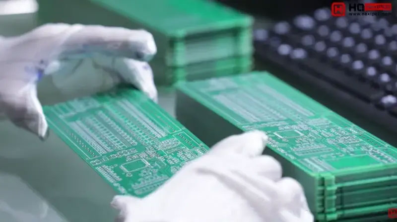
Mixed technology is the normal answer, not a compromise. Each joint is made the way that joint is best made.
Where it is used
Automotive applications include ignition and control circuits. Industrial automation equipment uses through-hole parts for drives and interfaces, and medical instruments use them where a joint has to be inspectable. Aerospace equipment, high-power LED lighting, and educational projects complete the list, and the common thread is either reliability, power, or the value of being able to see and touch the joint.
Manufacturing flow
The sequence runs from design and layout through drilling, which produces the plated and non-plated holes the design requires. Plating follows for multilayer boards, creating the connection between layers, and insertion places the components. Wave soldering or selective soldering then forms the joints, and inspection and test close the process.
For a complex multilayer through-hole board, registration and inner-layer inspection matter as much as the outer joints, because a hole that misses its pad cannot be repaired. The alloys and their process temperatures are described in our guide to lead-free versus leaded solder.
Design points
Pin spacing should be generous enough to prevent solder bridging between adjacent joints. Hole size has to match the lead diameter rather than exceed it, since an oversized hole produces a weak, poorly filled joint, and the pad and hole relationships are standardised in our guide to PCB pad design standards.
Thermal design is the third point: components that dissipate heat need copper area and, where the current is high, an adequate width in the surrounding traces. Wave solder compatibility is the fourth, which means no components shadowed from the solder wave and thermal relief where a pad connects to a large plane. Polarity markings belong on the legend for every polarised part, because a reversed electrolytic capacitor is a failure that assembly cannot detect. The wider sequence of assembly steps is covered under placement order and pad positioning.
Cost factors
Hole count and precision are the largest contributors, since each hole is a drilling operation and a tighter tolerance costs more. Board thickness and copper weight follow, then the surface finish, and finally the schedule: expedited delivery and certification requirements each add their own share.
Cost can be controlled without compromising the design by removing unnecessary holes, specifying the finish the assembly process actually needs, and choosing a supplier whose insertion and soldering processes match the order size rather than the other way round.
FAQ
Is through-hole technology still common? Yes, in automotive, industrial, aerospace, and power applications, where the mechanical and thermal properties matter more than board area.
Can through-hole and surface mount parts share one board? They commonly do, and many products use both. The assembly sequence has to protect the surface mount side during wave soldering, which is why selective soldering exists.
Is it always more expensive? The assembly is usually more expensive than surface mount for the same function, because insertion and soldering take longer and the board is larger. For a small number of heavy or high-current parts, it is often the cheaper and more reliable option.
How is the cost reduced? Fewer holes, standard finishes, and a supplier whose process suits the volume. Redesigning a part to surface mount is worthwhile only when the mechanical requirement allows it.