Motion Sensor PCB: Sensors, Layout, and Power Budget
Automatic lighting, security cameras, gesture control, and industrial safety systems all depend on the same underlying function: noticing that something moved. The board that does the noticing is built differently from a power or control board, because it has to sense a physical quantity, process a small signal, and act on it, often while running from a battery.
What a motion sensor PCB is
A motion sensor PCB integrates the sensing element, such as a passive infrared detector, an ultrasonic transducer, or an accelerometer, with the circuitry needed to condition and interpret its output. It is designed around three functions in sequence: sense, process, and respond.
The distinction from an ordinary board is not the components alone but the priorities. Sensitivity, noise immunity, and power consumption dominate the design, and each of them constrains the layout rather than only the bill of materials.
Sensor types
A passive infrared sensor detects the infrared radiation emitted by warm bodies and is the standard choice for automatic lighting and security systems. It is inexpensive and low power, and its weakness is that it senses heat rather than movement, so it responds to a person and not to a small robot.
An ultrasonic sensor transmits a burst of sound and listens for the reflection, which makes it accurate indoors and independent of temperature. A microwave sensor applies the Doppler principle, and because it operates at radio frequency it can detect movement through glass and plastic, which suits concealed installations.
Accelerometers and gyroscopes sense orientation, angle, and vibration rather than the presence of a person, and they appear in phones, wearables, and virtual reality hardware. The sensor choice determines the design complexity, the power budget, and the price of the finished board.
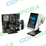
<img src="https://www.gopcba.com/wp-content/uploads/2021/03/h4_crs_overlay.png" alt="Motion sensor PCB with a PIR detector and control circuit” />
The sensing element sets the layout constraints. A detector that needs an unobstructed field of view has to be placed before anything else on the board.
The core blocks
A complete design contains five parts. The sensor module performs the detection. A microcontroller processes the signal and decides what to do, which is where filtering and threshold logic live. Power management keeps the supply stable whether the product runs from a battery or from a mains adapter.
Signal conditioning covers amplification, filtering, and interference rejection, and it is the block that decides whether the product triggers reliably or produces false alarms. The output interface completes the chain, driving an LED, a relay, a buzzer, or a wireless module, and it is often the largest contributor to the peak current drawn from the supply.
Where they are used
Smart lighting is the highest-volume application, where the board turns a person into a switching event. Security and surveillance equipment uses the same function to trigger recording or an alarm, and consumer devices apply it differently: a phone that silences itself when turned over and a fitness band that counts steps both rely on inertial sensing.
Industrial automation uses motion sensing to detect a person approaching machinery or to track the movement of goods, and automotive systems use it for occupant detection, gesture control, and blind spot monitoring. Each of those environments changes the weighting of the design priorities rather than the fundamentals.
Design points
Sensitivity and detection range are set partly by the sensor and partly by the layout, because the field of view depends on where the element sits and what surrounds it. A detector placed behind a component or close to a ground plane can lose range without any change to the circuit.
Immunity to interference is the second consideration. A board that triggers on an electromagnetic disturbance produces false alarms, which is why shielding and return path design matter more here than in a control board of similar complexity. The techniques are described in our guide to EMI suppression design principles.
Power is the third consideration, because many of these products run from a battery and have to remain armed for months. That means a low power microcontroller with an effective sleep mode, a supply design with low quiescent current, and attention to every path that can leak current while the product is idle. Compact layout and environmental adaptation complete the list, with the last of those often requiring a protective coating.
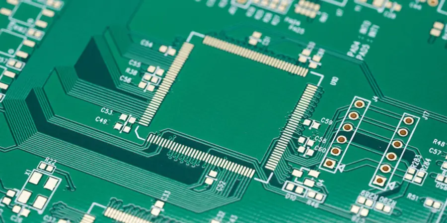
Detection range, immunity, and standby current are decided in layout. Each of them can be lost by placement long before the components are questioned.
Cost structure
A basic passive infrared board is the least expensive configuration, with the sensor and a small control circuit. An ultrasonic or microwave design costs more because the transducer and its drive circuitry are more complex, and a module that combines an inertial sensor with a microcontroller and a wireless interface sits highest of the three.
Layer count, component grade, and the amount of customisation then modify the price, and test complexity adds to it, because a sensing product has to be verified functionally rather than only electrically. Volume moves the unit price in the usual direction.
Selecting a manufacturer
Five factors decide whether a supplier is suitable. Quality certification is the first. Prototype and small-batch support is the second, because sensing products are tuned by iteration rather than finalised on paper. Experience with sensor module integration is the third, and it is what prevents the compatibility problems that appear when a detector is placed without regard for its mechanical requirements.
Lead time is the fourth, and customisation is the fifth: protection coating, preloaded firmware, and unusual board outlines are all common requests in this product class, and a supplier who handles them removes a scheduling risk from the project. The placement rules that keep small assemblies reliable are covered in our guide to placement order and pad positioning.
Service life and environment
A motion sensing board in a normal indoor environment typically serves five to ten years, with the figure depending on component quality and how often the device is triggered. Outdoor and industrial installations shorten that considerably if the board is unprotected, because moisture, dust, and thermal cycling attack the assembly.
As supplied, these boards are not waterproof. Conformal coating or potting is the standard answer, and the choice interacts with the sensor: a coating applied over a detector can change its response, so the coating schedule has to define exactly which areas are covered and which are kept clear. Those decisions are described in our guide to conformal coating for board protection.
A note on false triggers
False triggering is the failure mode that ends a product in the field. It usually comes from a supply that is not quiet, from a return path shared with a switching regulator, or from a detection threshold set too close to the noise floor. All three are design decisions rather than sensor limitations, which is why the layout review matters as much as the component choice.
FAQ
Can I design one myself? Yes. A basic sensing circuit is a reasonable project, and the layout constraints, a clear field of view for the detector and a quiet supply, are easier to satisfy than in most mixed-signal designs.
Is the board waterproof? Not by default. Protection comes from a conformal coating or from potting, and both have to be planned around the sensor opening.
How long do these boards last? Five to ten years in a normal environment, less where temperature cycling or contamination is present.
Can the same design be used in a wearable? Yes, with an inertial sensor rather than a presence detector. Inertial sensing boards are standard in watches, fitness bands, and virtual reality hardware.