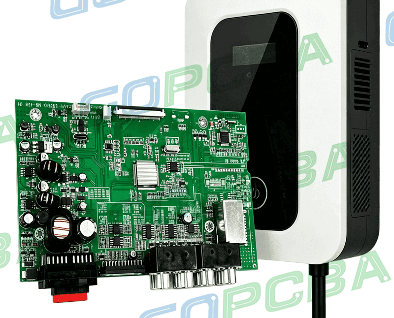
Designing a Microwave Transmitter PCB for Continuous Duty
A microwave transmitter runs hot, runs continuously and cannot tolerate a small error in the wrong place. At several gigahertz a fraction of a decibel of extra loss reduces the link margin, a few degrees of phase drift spoils a phased array, and a hot spot at a junction degrades the device that generates the power. The microwave transmitter PCB is where all of those effects are decided.
What Makes a Transmitter Board Different
A receiver can often tolerate a small amount of loss. A transmitter cannot, because loss in the board is loss in the signal being sent, and the power amplifier is already the most stressed component in the chain. The board also carries the highest continuous current on the radio side, so thermal and electrical design cannot be separated.
Reliability expectations are correspondingly higher. A transmitter in a base station or a satellite terminal is expected to run for years with no maintenance, so the design must be free of mechanisms that degrade with time, such as galvanic corrosion, whisker growth or a joint that fatigues under thermal cycling.
Material Selection
The two parameters that drive the choice are the dielectric constant and the dissipation factor. A stable dielectric constant keeps impedance and phase predictable, and a low dissipation factor keeps insertion loss small. PTFE based laminates give the best combination, at the cost of a difficult and expensive fabrication process.
Hydrocarbon ceramic materials sit between PTFE and ordinary epoxy. Their loss is low enough for many transmitter applications and their processing is closer to a conventional laminate, so they can be the practical choice where the link budget allows. The decision should be made from a loss budget rather than from a preference for the best material available.
Hybrid Stackups and Cost Control
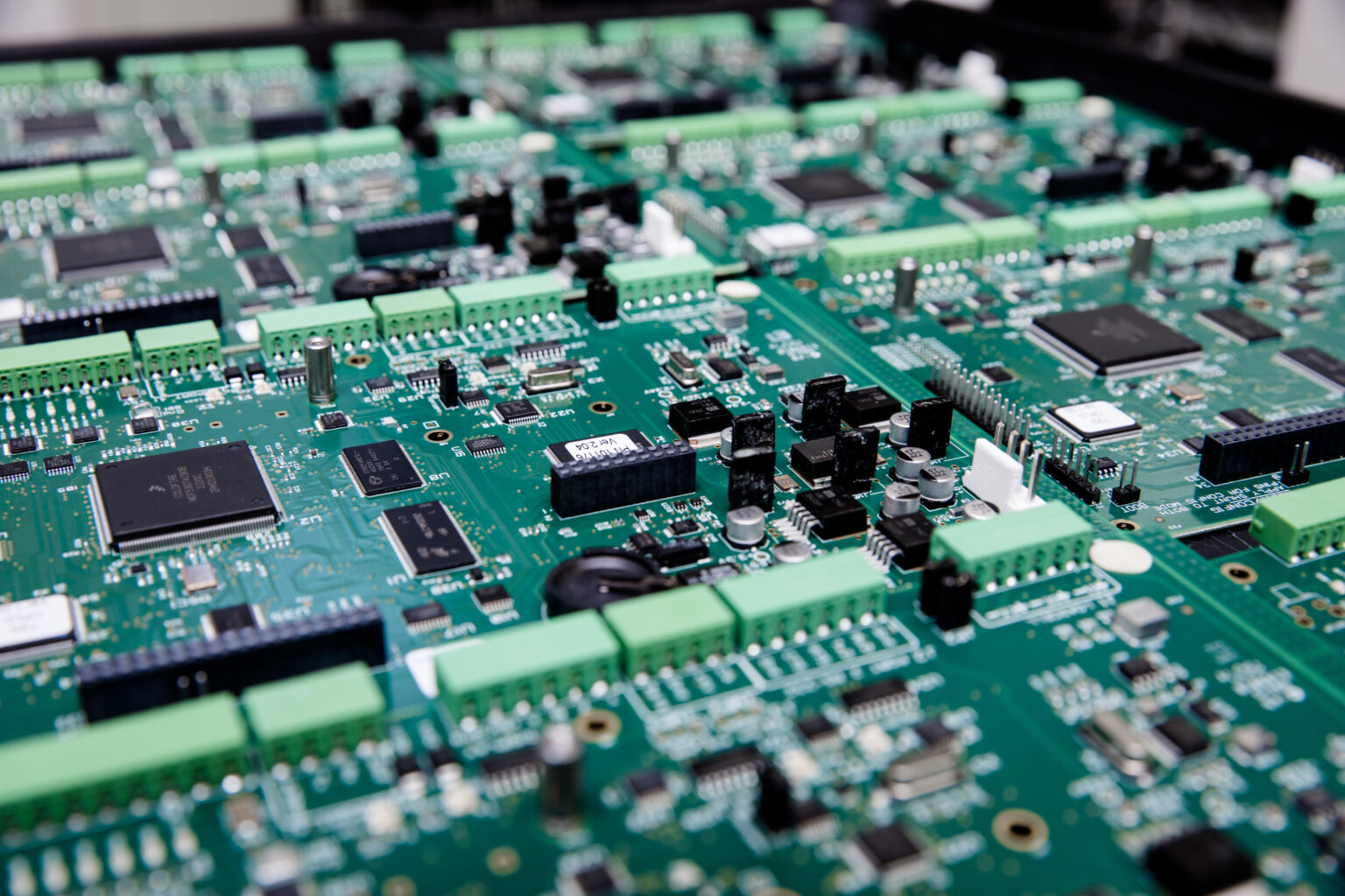
True PTFE everywhere is expensive, so most transmitter boards use a hybrid stackup. The radio frequency layers carry the low loss material and the control, digital and power layers use an ordinary laminate. The result is a board that meets the radio requirement at a fraction of the material cost.
Hybrid construction has its own problems. The two materials have different coefficients of expansion and different stiffness, so a poorly balanced stackup warps during lamination. The interface between them can also delaminate if the pressing cycle is wrong, so the stackup should be designed with the fabricator and the lamination checked on a first article.
Impedance Control and Line Choice
Impedance control on a transmitter board is tighter than on a digital board, commonly plus or minus five per cent, because the impedance sets the matching of the whole chain. Every interface in the path, from the connector to the amplifier input to the antenna feed, must present the same impedance or the power reflects instead of radiating.
The transmission line geometry follows from the layout constraints. Microstrip is easy to route and radiates a little, stripline is fully shielded but confined to inner layers, and grounded coplanar waveguide combines a top side ground with a close reference and suits components that need a low inductance ground right at the pad. The trade offs are compared in microstrip and stripline routing.

Power Handling and Thermal Management
The power amplifier dissipates a large fraction of the power it produces, and that heat has to leave through the board. Thermal management in this context means a solid copper path under the device, a dense array of filled vias to a thermal plane, and a substrate that can carry the heat without softening or delaminating.
Junction temperature is the number that matters, and it is set by the sum of the die to case resistance, the interface material, the via array and the heat sink. On a transmitter board the via array is often the weakest term, so a modest improvement there buys more than a larger heat sink elsewhere.
Grounding and Isolation
A transmitter needs a ground reference that is continuous under every radio frequency line, with stitching vias along the edges of the coplanar structure to keep the two ground planes at the same potential. Gaps in that ground, however small, produce radiation and change the impedance of the line above them.
Isolation between the radio section and the digital control is equally important. The control circuit can be screened with a ground fence, and its clock harmonics should not be able to find a path into the radio section. The broader principles are set out in EMI suppression design principles.
Fabrication and Assembly
PTFE behaves differently from epoxy at every step. It is softer, so drilling produces rougher walls and requires controlled parameters. It expands more with temperature, so hole wall quality and registration need closer attention. It does not tolerate the same desmear chemistry, so the plating process has to be adapted.
Assembly follows the same logic. A transmitter board often carries a large metal backed device that must be soldered with a controlled void content, and the reflow profile has to account for the thermal mass of the ground plane. Vias that must be flat under a component are usually filled and capped, and the options are set out in blind and buried via stack selection.
Qualification and Reliability
Qualification for a transmitter board is usually built around thermal cycling, power cycling, vibration and humidity with bias. Power cycling is the most revealing for the amplifier, because it drives a steep thermal gradient through the via array and the die attach rather than a uniform temperature change.
Acceptance criteria should be defined before testing starts. Insertion loss and phase are measured before and after each exposure, and the pass criterion is the allowed drift rather than a simple go or no go. A board that survives testing but has shifted its loss by half a decibel has still failed to meet the link budget.
Test and Measurement Setup
Verifying a transmitter board needs a measurement plan that matches the frequencies involved. A vector network analyser with calibrated reference planes at the board connectors measures insertion loss and return loss, and a power meter confirms the output at the operating point. Without calibration at the correct reference plane, the fixture contributes more error than the board does.
The measurements should be recorded per board rather than per batch, because the variation between boards is what shows whether the process is in control. A tight distribution of insertion loss across a panel is a better indicator of a stable fabrication process than a single good result, and it gives the designer something to compare against after a process change. Thermal imaging under load completes the picture by showing where the heat actually goes, which is frequently not where the layout intended.
FAQ
Is PTFE always necessary? No. Where the link budget allows the extra loss, a hydrocarbon ceramic laminate performs well and is easier to process. PTFE is reserved for the highest frequency and lowest loss requirements.
What impedance tolerance should be specified? Plus or minus five per cent is typical for a transmitter board, with a test coupon on the panel. Looser tolerances are cheaper but consume link margin.
Can digital and radio circuits share one board? They can, with a hybrid stackup and a proper ground strategy. The radio frequency section should be isolated with its own reference plane and a screened boundary, and the two should not share a return path.