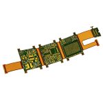
LED Strip Board Manufacturing: Rigid Bars and Flexible Strips
An LED strip is a light source that looks simple and is not. The board carries a line of emitters, a driver, and a return path that has to deliver the same current to the far end of the strip as it does to the near end, all inside a form factor that may be a metre long and a few millimetres wide.
This article looks at how an LED strip board is actually specified and built, how the rigid and flexible versions differ in design and assembly, and which of the choices on the drawing decide whether the light output stays uniform after a year of continuous operation.
Rigid LED Bar or Flexible Strip: Choosing the Substrate
The first decision is mechanical. A rigid LED bar is built on a normal rigid board, usually FR-4 or an aluminium-backed material, and it can be screwed, clipped or slid into an extrusion. It cannot be bent, which makes it suitable for linear fixtures, display backlights and machine vision lighting where the geometry is fixed and the board also acts as a heat spreader.
A flexible strip is built on polyimide and can be folded, coiled and cut to length. It fits into curved housings and narrow channels, and it is supplied on reels for automated placement. The trade is thermal: a flexible circuit has far less copper and no metal backing, so the same emitter driven at the same current will run hotter on a strip than on a rigid bar.
Assembly Route: Chip Placement Versus Through-Hole LEDs
The assembly method follows the substrate. Surface mount emitters are placed by machine, reflowed with the rest of the components, and are held by solder joints on all sides, so they resist vibration and thermal cycling well. Through-hole emitters are inserted by hand or by a dedicated machine and soldered individually, which is slower and leaves the leads as the only mechanical connection.
The practical consequence is uniformity. A machine-placed line has consistent pitch and orientation, so the light output is even along the board. A hand-assembled line shows the variation immediately, particularly where emitters are inserted at slightly different depths or angles. For anything beyond a short decorative run, surface mount placement is the route that keeps the finished product consistent.

The Driver, the Voltage Drop and Current Uniformity
A constant current driver is what keeps the light output stable as the strip warms and as the supply voltage moves. Driving emitters from a fixed voltage instead allows the current to rise as the forward voltage falls with temperature, which is the mechanism behind the familiar runaway failure in which one emitter in a series string fails and the rest follow.
On a long board the copper itself becomes part of the circuit, which is why the trace width and current calculation has to be run on the feed and return tracks rather than on the signal tracks alone. The track feeding the string has resistance, so the current arriving at the far end is lower than at the near end and the emitters at the end are dimmer. The fix is to widen the feed and return tracks, to feed the string from both ends, or to break a long strip into shorter segments each with its own driver. Segmenting also limits the effect of a single failure.
Thermal Management on a Long Narrow Board
Thermal management on an LED strip is limited by the copper available. A rigid bar can use a metal-core or aluminium-backed board so that heat passes through the dielectric into the metal and out to the housing. On such a board the dielectric layer is thin and thermally conductive, and its thermal resistance is the parameter that matters, not the thickness of the aluminium.

A flexible strip has no such path. Heat must spread laterally through the copper, so the thermal design becomes a question of copper area per emitter and the spacing between emitters. Adding thermal vias under each emitter helps only if there is somewhere for the heat to go on the other side. Keeping the drive current below the rating, and spacing emitters further apart, is often more effective than any layout trick.
Sealing, Potting and Moisture Protection
Outdoor and wet-location strips are potted or encapsulated, and the potting compound has to be chosen for the optical and thermal requirements at the same time. A compound that is opaque protects the electronics and blocks the light, so the emitter area is usually left clear while the driver and the terminations are flooded.
The weak points are the ends. Where a strip is cut and rejoined, or where a cable enters, the seal is only as good as the joint, and moisture that reaches the copper will cause corrosion and eventually a change in the current path. Solder joints should be smooth and fully wetted, the cable entry should be strain-relieved, the conformal coating used to protect the board should be compatible with the potting compound so that the two do not delaminate, and the potting and dispensing materials should be specified by their cured properties rather than by their uncured viscosity alone.
Ageing Test and End-of-Line Checks
An LED strip is normally aged before it ships, because the failure rate of a light source is highest in the first hours and lowest afterwards. A burn-in at rated current for several hours, followed by a low-voltage illumination check, will catch a cold solder joint, a reversed emitter and a partially open track before the product reaches a customer.
The low-voltage check is worth explaining. Illuminating the strip at a reduced voltage lets the operator see the emitters while the current is too low to damage anything, and a single dark emitter in a string is obvious. Measuring the total current at rated voltage complements the visual check, because uniform dimming from a high-resistance feed track does not show up as a dark emitter at all.
Designing the Board for Cutting and Joining
A flexible strip is sold in fixed lengths and cut at marked positions, which means the board has to be laid out so that every cut point leaves a complete, functional segment with its own driver or at least its own current-limiting element. The cut marks are a manufacturing requirement as much as a user instruction; a strip that can be cut between the wrong pair of pads will be returned as faulty.
Joining is the same problem in reverse. Where segments are linked, the connection has to carry the full string current, so the pads need enough copper area for a reliable solder joint and the joint should be supported mechanically. Connectors help, but the board still needs to be designed so that the connector footprint, the pad and the track all carry the current without a local hot spot.
FAQ
Can a flexible strip be used at the same current as a rigid bar? Not usually. The flexible substrate has much less copper and no metal backing, so the same current produces a higher junction temperature. Derate the drive current, or spread the emitters further apart, if the strip has to run continuously.
Why do the emitters at the end of a long strip look dimmer? Because the feed track has resistance and the current falls along it. Widening the copper, feeding the strip from both ends, or splitting it into shorter driven segments all correct the problem, and the last option also limits the impact of one emitter failing.
Does potting an LED strip change its colour? It can. The compound has its own transmission spectrum and can shift the apparent colour temperature, especially if it yellows with heat. Choose an optical-grade material with a defined transmission curve, and verify the colour after curing rather than relying on the uncured sample.