Copper Pour on Outer Layers: When It Helps and When It Hurts
Pouring copper over the empty area of an outer layer is one of those steps that is usually recommended and rarely explained. Done well it improves shielding, spreads heat and helps the board survive reflow. Done badly it creates isolated slivers of copper that behave as antennas, changes the impedance of the traces beside it and makes rework harder. The decision depends on the stack-up and on the signals involved.
What a Copper Pour Is For
A copper pour is a large area of copper, normally connected to ground, that fills the space between traces and components on an outer layer. Its benefits are straightforward: it provides additional shielding for the inner layers, it suppresses noise that would otherwise couple into and out of the surface, it improves the ability of the board to spread heat, and it reduces the amount of etchant consumed during fabrication. It also balances the copper distribution across the two outer layers, which limits the differential stress that appears during reflow and reduces the tendency of a thin board to bow or twist.
None of these benefits require the pour to be continuous. They require it to be well connected to the ground reference, which is where many designs go wrong.
When a Pour Becomes a Problem
An outer layer is crowded with components and signal traces, so a pour on that layer is divided into fragments. A fragment that is connected to ground at one end and open at the other behaves as an antenna, and the thin, long slivers are the worst offenders. The remedy is either to connect each fragment to the ground plane through enough vias that it cannot resonate, or to remove the fragment entirely. Leaving it in place and hoping is not a remedy.
A second problem appears near pads. When a component pin is connected to the pour with a solid connection, the heat of a soldering iron is conducted away as fast as it is applied, and both hand soldering and rework become difficult. Thermal relief spokes solve this by narrowing the connection, at a small cost in impedance.

The Cost in Routing Channels
Every via placed to tie the pour to the ground plane consumes routing space. On a dense board the vias required to make a pour electrically sound can block the channels that the remaining signals need, which forces additional layers or longer routes. This is the point at which a designer has to decide whether the pour is serving the design or the design is serving the pour.
Where the pour cannot be stitched properly, removing it is a legitimate choice. An absent pour is a predictable structure; a poorly stitched one is not.
Two-Layer Boards Are a Different Case
On a two-layer board, the pour is usually the ground reference itself. The common arrangement is a ground plane on the bottom, with components and the supply and signal routing on the top. For high-impedance circuits and for analogue sections, including conversion circuits and switching supplies, this arrangement is a good one, and the pour is what makes the return path predictable.
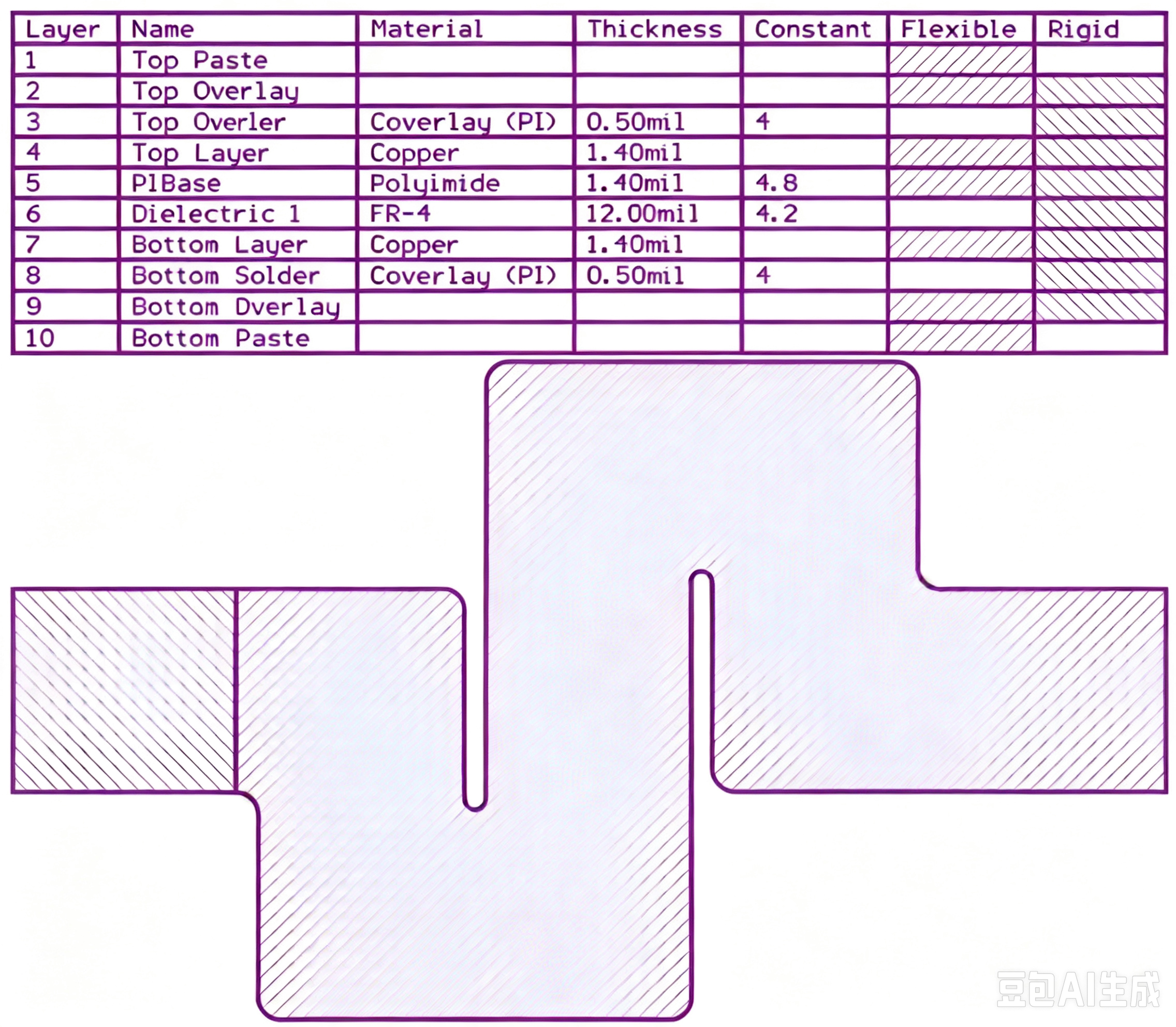
The distinguishing factor is the separation between the signal and its reference. On a two-layer board the spacing is large, commonly around sixty mil, so the return current spreads across a wide area and a continuous ground pour along the route is what keeps the loop small. Our layer assignment guidance covers how this changes when the board becomes multilayer.
Multilayer Boards With Complete Planes
Where a multilayer board already has complete power and ground planes, an outer pour adds much less. The reason is geometric: the return current of a microstrip trace takes the lowest-impedance path, which is the reference plane directly beneath the trace rather than a piece of copper beside it. If the trace is less than about ten mil from its reference plane, the pour on either side of it does very little, and if the pour comes close to the trace it changes the characteristic impedance of the line.
An outer pour on such a board can therefore reduce crosstalk only marginally, while introducing two new problems: impedance discontinuities where the pour edge crosses near a trace, and narrow fragments that radiate. High-speed digital boards with complete internal planes are the case in which the pour is most often omitted.
Practical Rules for Deciding
Where a pour is used, keep it at least four times the trace width away from high-speed signals so that the characteristic impedance of those traces is not disturbed. Stitch the pour to the main ground plane with vias spaced at about one tenth of a wavelength of the highest signal frequency, which keeps the potential of the pour consistent at the frequencies that matter. If the stitching cannot be placed, reduce the pour rather than leaving it unstitched.
Where the board is sparse and the high-speed content is low, a pour on both outer layers is usually the better choice, because it improves reflow behaviour and mechanical stability at very little electrical cost. On a dense high-speed board with internal planes, the answer is often to leave the outer layers free of pour except around specific sensitive areas where a local shielding requirement justifies it.
Making the Decision Explicitly
The pour decision belongs in the design review rather than in a default setting. State whether each outer layer is poured, what the pour is connected to, how often it is stitched and how far it is held away from controlled-impedance traces. A pour applied by habit, without those answers, is a source of problems that are difficult to diagnose later because the pour is invisible in the schematic and easy to overlook in the layout.
Our design release checklist covers the pour and stitching checks, the EMI immunity design material explains how fragments radiate, and the high-frequency laminate notes describe the materials used when the impedance requirement is tight.
FAQ
Should every board have a copper pour on both outer layers? No. Boards with internal power and ground planes and a significant quantity of high-speed routing often perform better without an outer pour, because the pour adds fragments and impedance discontinuities without contributing much shielding. Boards that are sparsely populated, boards without internal planes and boards with analogue or high-impedance circuitry generally benefit from a pour on one or both outer layers.
How often should a ground pour be stitched with vias? The spacing should be short relative to the highest frequency of interest, which is normally expressed as about one tenth of a wavelength in the laminate. In practical terms this produces a maximum spacing of a few millimetres on a high-speed board and considerably more on a low-frequency board. The purpose is to keep the potential of the pour uniform, so any fragment that cannot be stitched at that spacing should be removed.
What does gopcb need to know about the pour before fabrication? We need to know which layers are poured and how the pour is connected, because it affects the copper balance that controls warp during lamination and reflow. Customers who specify stitching density and the clearance from controlled-impedance traces give us enough information to check the design against the fabrication process, which is where pour-related issues usually surface.