Capacitor Selection for PCB Design: Types and Behaviour
A capacitor is the simplest component on the board and the one whose behaviour is most often taken for granted. It stores charge, it blocks direct current, it passes changing current, and it does all of those things imperfectly. Capacitor selection follows from understanding which of those properties the circuit is relying on, and the placement then follows from the impedance the capacitor presents at the frequency that matters.
What a Capacitor Does in a Circuit
Apply a potential to a conductor and it takes on charge. The amount of charge it holds for a given potential depends on its geometry, and that ratio is its capacitance, measured in farads. Two parallel metal plates separated by an insulating dielectric, with connections brought out to each, form the component known as a capacitor. The dielectric is part of the definition rather than an accessory: it is what allows a large capacitance in a small volume, and it is also the part that can be destroyed by excessive field strength.
Two consequences follow from the way charge is stored. The first is that storing energy takes time, so the voltage across a capacitor cannot change instantaneously. The second is that a capacitor has two ratings that matter more than any other: its capacitance and its voltage rating. Exceed the second and the dielectric breaks down, the component shorts, and the failure usually takes something else with it.
The RC Time Constant
Charging a capacitor through a resistor produces the classic exponential curve. At the instant the supply is connected, the charging current is at its maximum and the voltage rises fastest. As the voltage across the capacitor rises, the current falls, and the rate of rise falls with it, until the capacitor reaches the supply voltage and the current reaches zero.
The rate is set by the product of the resistance and the capacitance, which is the RC time constant. A larger series resistance means a smaller charging current and a longer time to charge; a larger capacitance means more charge is required for the same voltage, which also lengthens the time. Discharging through the same resistor produces the mirror image of the same curve. This single relationship explains reset timing, filter response, and the behaviour of a supply that has to charge a large capacitance on power-up.
Capacitive Reactance and Filtering
A capacitor passes changing current and blocks steady current, and it does so in a way that depends on frequency. Apply a direct voltage and, once the charge has settled, nothing appears at the other terminal. Apply an alternating signal and the same signal passes, with the amplitude at the output rising as the input frequency rises. The mechanism is the delay in the voltage across the plates: when one plate changes potential quickly, the other follows with the same motion, offset by the capacitor voltage, so the signal is transferred even though no charge crosses the dielectric.
Because the transfer improves with frequency, a capacitor combined with a resistor forms a filter. Configured one way it passes high frequencies and rejects low ones, which is a high-pass filter and is used to remove the low-frequency content of a signal. Configured the other way it passes low frequencies and rejects high ones, which is a low-pass filter and is used to remove noise, ripple, and high-frequency content. Every decoupling capacitor on a board is an example of the second case.
Choosing Between Types
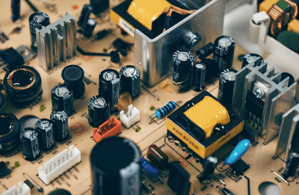
Three families cover most board designs, and the differences are practical rather than theoretical. Aluminium electrolytic capacitors are polarised, so the positive terminal has to be connected to the higher potential. They offer large capacitance and tolerate significant ripple current, but their tolerance is wide, their leakage is comparatively high, and ordinary types are unsuitable at high frequency and low temperature, generally above about 25 kHz.
Tantalum electrolytic capacitors are also polarised. Their temperature behaviour, frequency behaviour, and reliability are better than a conventional electrolytic, with very low leakage, a long life, and a small tolerance, and they pack the largest capacitance-voltage product into the smallest volume. Their weaknesses are a poor tolerance to ripple current, a tendency to fail short, and a higher price. Multilayer ceramic capacitors are the most widely used type on modern boards: they are stable across temperature and frequency, have low loss, and last a long time, but they cannot be made in large values. The application decides which of the three fits, and the electrical characteristics and placement rules for the parts around a switching supply are covered in DC-DC converter layout and routing.
Placement Rules That Actually Matter
A capacitor is only as effective as the path connecting it to the circuit. The loop formed by the capacitor and the device it serves has its own inductance, and that inductance sets the frequency above which the capacitor stops working. The capacitance may be adequate and the part may be correctly chosen, and the loop can still make it useless at the frequency where the noise actually appears.
That is why placement rules are strict rather than advisory, and why the return path matters as much as the trace; the underlying reasoning is developed in ground current and harmonic distortion. A decoupling capacitor belongs as close as possible to the pin it serves, with the shortest and widest connection to both the supply and the ground. Every millimetre of trace, and every via in that path, adds inductance in series. The same reasoning governs the connection between a filter capacitor and the pad it feeds: the trace should be short and wide, because a long thin connection defeats the component that was chosen to do the job.
Voltage Rating and Derating
The voltage rating is a limit, not a target. Operating a capacitor close to its rating shortens its life and, for a dielectric with a strong voltage dependence, changes its capacitance. Ceramic parts in particular lose a significant fraction of their nominal capacitance as the applied voltage approaches the rating, so the value marked on the reel is not the value the circuit sees.
Two further effects belong in the same calculation. Temperature changes the capacitance, and for some ceramic formulations the change is large enough to matter across the operating range. Ageing does the same thing over a longer period. A design that specifies a capacitor by its nominal value alone, without considering the voltage coefficient and the temperature behaviour, finds that the value in the circuit is lower than the one on the schematic, and that the margin it counted on is not there.
What Goes Wrong in Practice
A capacitor fails in one of four ways: capacitance falls, capacitance disappears, leakage increases, or the part shorts. The symptom depends on the role it plays. A failed filter capacitor on a switching supply may prevent the supply from starting, or may leave the output poorly filtered so that logic behaves erratically and the unit works only sometimes. A shorted capacitor on a supply rail produces a rail that will not come up, and finding it becomes a matter of locating the component drawing the fault current.
Heat accelerates most of these failures. Capacitor life falls as ambient temperature rises, and the effect applies to every type, which is why a component placed beside a heatsink or a power device is a candidate for early failure long before the rest of the board. Keeping capacitors out of the hottest regions, and choosing a temperature rating that suits where they end up, is more effective than buying a higher-grade part and placing it in the heat. Related placement and layout practice is collected in low-cost signal quality improvements.
FAQ
Why can the voltage across a capacitor not change instantly? Because storing charge takes time. The current that flows is proportional to the rate of change of voltage, so an instantaneous change would require infinite current.
What does the time constant of an RC circuit tell me? How quickly the capacitor charges or discharges. It is the product of resistance and capacitance, and a larger value in either lengthens the response.
Why is a ceramic capacitor sometimes much lower than its marked value? Because ceramic dielectrics lose capacitance as the applied voltage rises, and the value also moves with temperature. The marked value is measured under small-signal conditions.
Which capacitor type should be used for supply filtering? Usually a combination. A large electrolytic or tantalum handles the bulk energy and the low-frequency ripple, and ceramic capacitors close to the device handle the fast transients.