Signal Quality Improvements That Cost Almost Nothing
Improving signal quality is usually presented as a choice between spending money and accepting compromise. Add more layers, add termination, add a metal shield, add a faster material. In practice a large part of the improvement available to any design is free, because it comes from decisions that cost nothing except attention: where components sit, how functions are divided, and how the copper is arranged between them.
Placement Is the Cheapest Lever
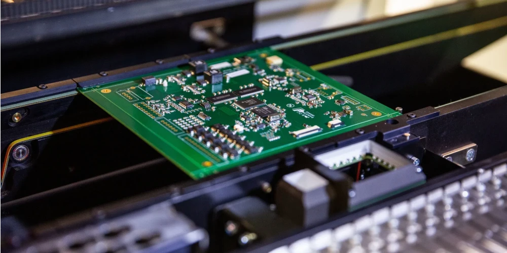
Component placement determines the length of every critical path, and length is the variable that most affects signal behaviour. A high-speed processing device, a high-frequency oscillator or an analog front end placed next to a power entry point inherits the noise of the supply and the switching activity around it. The same part placed at the periphery of the board, with space around it for filtering and shielding, performs measurably better.
The mechanism is not mysterious. Distance reduces the coupling between a sensitive circuit and the currents that disturb it, and it also reduces the parasitic capacitance between the sensitive nodes and their surroundings. A radio frequency front end at the edge of a board has room for a filtering network and an isolation structure around it that a part in the middle of the digital section does not.
Placement also determines routing cost. A part placed to shorten its critical connections reduces the number of layer transitions and vias the route requires, which reduces cost while improving performance. The two goals are usually aligned rather than opposed.

Functional Partitioning
Dividing the board into functional regions is the second free improvement. Analog signal processing belongs in one region, digital processing in another, and power management in a third. Keeping a gap between the regions, with coupling elements placed where signals cross the boundary, limits the interaction between them without requiring any additional material or process.
An industrial control board with analog sensor conditioning and a high-power motor drive makes the argument clearly. Placing the two functions at opposite ends of the board, with isolation between them and decoupling capacitors at the boundary, achieves most of what a shielding can would achieve at a fraction of the cost, and it does so without adding a component that must be sourced, placed and grounded. The measurement chain then sees a quiet reference, and the drive stage is no longer injecting its switching noise into the sensor path.
The partitioning principle extends to the reference planes. Where the board contains both analog and digital circuitry, the ground arrangement adopted at placement time is what determines whether the analog reference stays clean, and the reasoning behind it is set out in this discussion of mixed signal design guidelines.
Decoupling and the Cost of Getting It Wrong
Decoupling capacitors are cheap; the layout that makes them effective is also cheap. What costs money is discovering, after the first prototype, that the decoupling does not work because the capacitor sits 20 millimetres from the pin it serves. The loop formed by the capacitor, the supply pin and the ground plane is what delivers transient current, and the inductance of that loop sets the frequency above which the capacitor stops helping.
The improvement available at no cost is to place each capacitor against the pin it serves, with its ground connection made directly to the plane through a via adjacent to the pad. The same component moved a few millimetres and connected through a longer trace loses most of its value, and no specification on the parts list records that loss. Where a device has multiple supply pins, the small capacitors belong at the pins, and the bulk capacitance can be shared at a distance.
Edge Rate and Termination
Faster edges are not always better. A signal with a slow edge radiates less, couples less into neighbouring traces and stresses the receiver less, provided the receiver can still resolve it within the timing budget. A small series resistor close to the driver slows the edge, damps ringing and reduces emissions, and the cost is a fraction of a cent.
Termination is the same argument applied deliberately. Series termination at the source is inexpensive and effective for point-to-point nets. Parallel termination costs a continuous current, and AC termination costs a capacitor, so the choice should follow from the topology rather than from habit. The physics that makes these measures effective is the same physics that governs emissions, and it is described in this article on EMI suppression design principles.
Reference, Return Path and Stack Choices
A signal is only as good as the reference it runs over. Making the return path continuous costs nothing at the routing stage but saves a great deal of trouble later: keeping the plane unbroken under every fast net, avoiding plane splits beneath signals, and providing a companion ground via wherever a signal changes layers. The consequences of ignoring this are examined in the article on ground current and harmonic distortion.
Layer arrangement is the one item on this list that does cost money, since additional layers increase the board price. But the cost is often lower than the alternatives, and a stackup chosen so that every signal layer has an adjacent plane removes the need for many of the other measures. The trade-offs involved are described in this discussion of layer stackup design.
What to Check First
If a design needs better signal quality and the budget will not move, start with placement: move the sensitive parts away from the noise sources and shorten the critical routes. Then partition the board by function and set the boundaries before routing. Then verify that every decoupling capacitor is adjacent to the pin it serves, and slow the edges that do not need to be fast. Those three steps are free, and in most designs they recover more performance than any single component change. The remaining improvements do cost something, but they should be considered only after the free measures have been exhausted, because a design that has poor placement will not be rescued by an expensive material or an additional layer. Where the free measures are insufficient, the next step is usually a change of reference geometry rather than a change of component, and the reasoning behind that choice is examined in this article on ground current and harmonic distortion.
FAQ
What is the single most effective free improvement to signal quality? Component placement. It determines the length of every critical path, the distance from sensitive circuits to noise sources and the routing complexity, so it influences more of the final performance than any other decision that costs nothing.
Does partitioning a board cost anything? Not in material or process. It is a placement decision, and its cost is the design time needed to analyse where the boundaries should fall. The return is a reduction in coupling between sections that would otherwise require shielding or filtering to control.
Can slowing a signal edge really improve performance? Yes, if the receiver still meets its timing. A slower edge reduces crosstalk, radiated emissions and ringing, and a series resistor at the driver is usually enough to achieve it. The limit is the setup and hold margin of the receiver, not the aesthetics of the waveform.