Metal Core PCB or Ceramic Substrate: How to Choose
When a component produces more heat than an ordinary laminate can carry away, the board itself becomes part of the thermal solution. Two families answer that requirement: the metal core PCB, which uses an aluminium or copper base under an insulating dielectric, and the ceramic substrate, which uses alumina or aluminium nitride as the insulating body. Both move heat far better than FR4, and both are considerably more expensive. Deciding between them comes down to how much heat must move, how much voltage must be isolated and how closely the board must match the expansion of what is mounted on it.
Two Answers to the Same Problem
A metal core board keeps a conventional printed circuit on top and uses metal underneath as a heat spreader. The circuit is built on copper foil bonded to an insulating layer, and that layer is bonded in turn to a thick aluminium or copper plate. Heat travels through the dielectric by conduction and then spreads laterally through the metal, where it can be transferred to a heatsink or a chassis.
A ceramic substrate removes the polymer dielectric entirely. The circuit is metallised directly onto alumina or aluminium nitride, so the insulation between the conductor and the base is the ceramic itself. There is no organic layer to break down at temperature, no resin to outgas and no glass transition, which is why ceramic is chosen when the operating temperature or the reliability requirement goes beyond what a polymer can survive.
How a Metal Core PCB Is Built
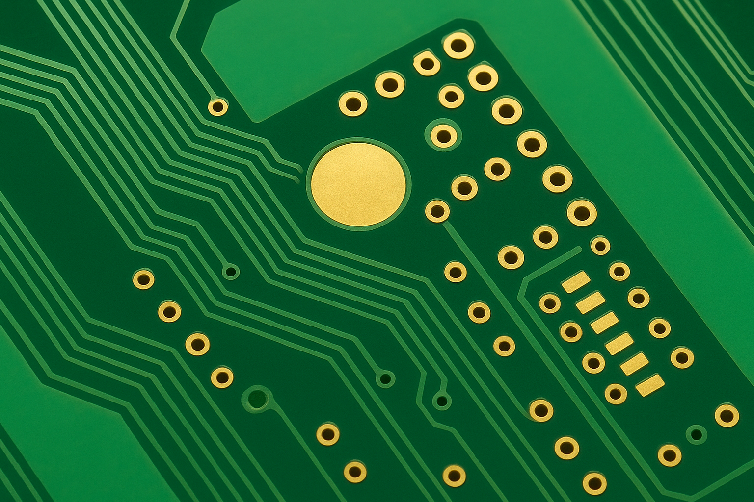
The base is usually aluminium because it is light, inexpensive and easy to machine, with copper used where the highest conductivity is needed. A thin dielectric, often filled with ceramic particles to raise its conductivity while keeping the breakdown strength, bonds the copper foil to the base. The circuit is then imaged and etched as usual, and a solder mask and finish complete the board.
Because the process resembles ordinary PCB fabrication, metal core boards support fine features, multilayer constructions and plated through holes into the metal where an isolated thermal pad is needed. The metal also gives the board mechanical stiffness, which is useful for long LED strips and for boards that must stay flat while carrying heavy components.
How a Ceramic Substrate Is Built
Ceramic substrates are made by direct bonded copper, active metal brazing or thick film printing, depending on the conductor thickness and the precision required. Alumina offers good insulation and moderate thermal conductivity at a reasonable cost, while aluminium nitride raises the conductivity several times over and brings the coefficient of thermal expansion close to silicon.
The advantage of the ceramic route is that the dielectric is also the structure. There is no adhesive to degrade, no dielectric to delaminate and no polymer to limit the operating temperature, so the same board can survive soldering at high temperature, repeated thermal cycling and continuous operation well above the range that a metal core board tolerates.
Thermal Conductivity Compared
The numbers separate the two families clearly. A standard metal core dielectric conducts in the region of one to three watts per metre kelvin, and the aluminium base beneath it conducts around two hundred, so the dielectric is the bottleneck in the path. High performance filled dielectrics improve that figure but rarely reach beyond a few watts.
Alumina conducts around twenty four watts per metre kelvin through the whole thickness, and aluminium nitride reaches between one hundred and seventy and two hundred. Because the insulating layer is not a separate thermal resistor, the heat path is short and direct, which is why ceramic is preferred for laser diodes, power modules and devices where the junction temperature margin is small.
Electrical Isolation and Voltage
Isolation is where the metal core board fights back. Its dielectric layer is thin and can be engineered for a specified breakdown voltage, and the metal base can be connected to a chassis or left floating as the application requires. That makes it convenient for mains connected LED drivers, where a defined isolation barrier is mandatory and the metal base is also the thermal interface.
Ceramic offers excellent dielectric strength as well, but the achievable value depends on the ceramic thickness and the metallisation process. It is usually chosen where isolation and thermal performance are both critical and where the assembly can tolerate a brittle substrate, since a ceramic tile cracks rather than bends under mechanical overload.
Expansion Matching and Reliability
Thermal cycling is the test that separates the two in service. The aluminium base of a metal core board expands much more than the silicon die or the ceramic capacitor mounted on it, so the solder joints and the dielectric layer carry the strain. Large area devices on a metal core board therefore need careful attention to the dielectric thickness and to the joint geometry.
Aluminium nitride matches silicon closely and alumina is reasonably close, so a bare die on a ceramic substrate sees far less differential movement. That is the reason ceramic dominates in power modules and optoelectronics, where a few thousand cycles at large temperature swing would otherwise destroy the attach layer.
Weight, Size and Cost
Metal core boards are mechanically robust, easy to mount with screws and inexpensive relative to ceramic for moderate thermal loads. They are also heavier than an equivalent laminate, and the aluminium base makes them unsuitable for a flexible or a very thin assembly. Their cost sits well above FR4 but comfortably below a ceramic tile of the same area.
Ceramic is the more expensive option by a wide margin, and the panel size is smaller, which limits how many boards can be produced per run. It is justified where the thermal or reliability requirement cannot be met any other way, and where the volume is high enough that the cost per unit is amortised across a long product life. Our notes on aluminium versus FR4 and high temperature PCB materials cover the neighbouring choices.
Specifying the Choice on a Drawing
Whichever family is selected, the drawing has to state the parameter that drives the decision. For a metal core board that means the dielectric thermal conductivity, the dielectric breakdown voltage, the base metal and its thickness, and whether the base is connected to a net or left floating. For a ceramic substrate it means the ceramic material and purity, the conductor system and its thickness, and the maximum operating temperature the assembly must survive.
Both need a thermal test that reflects the application rather than a generic figure. A device soldered to the board and run at its rated power, with the case or the chassis held at the expected ambient, tells far more than a datasheet conductivity value. Asking for that measurement on the first article, together with a thermal cycle test, is what converts a plausible material choice into a design that will hold up in production.
FAQ
Is a metal core PCB better than a ceramic substrate? Neither is better in general. Metal core suits moderate thermal loads with a defined isolation barrier and a chassis mount, while ceramic suits high power density, high temperature and close expansion matching to a die.
Can a metal core board be multilayer? Yes. Multilayer metal core constructions are built with the circuit layers above the dielectric and the metal base acting as the thermal and mechanical core, though the process is more demanding than a single sided build.
When is ceramic the only option? When the operating temperature exceeds what a polymer dielectric can survive, when the die must be attached directly to the substrate, or when thermal cycling with a large temperature swing would otherwise destroy an adhesive layer.