10-Layer HDI PCB: Stackup, Microvia and Manufacturing Guide
A ten layer board with through vias can already carry a dense design. What it cannot do is carry that density in a small area, because every through via consumes routing space on every layer it passes through. High density interconnect solves that by replacing the through via with small drilled holes that connect only the layers they need to connect, and at ten layers the combination of high routing density and microvia technology is what makes modern handheld and infrastructure products possible.
Why Ten Layers with HDI
The layer count and the via technology solve different problems. Layers provide the planes needed for power distribution and the routing channels for the signals, while microvias provide the interconnections without consuming horizontal space. A design that needs both high pin count and a compact outline usually ends up at ten layers with one or two build up stages rather than at a larger through via board.
Signal integrity benefits as well. A microvia has a much shorter barrel than a through via, so the stub that reflects energy back into the channel is smaller, and the impedance discontinuity at the via is reduced. On multi gigabit interfaces that difference shows up directly in eye height, which is why HDI is common in server, switch and accelerator designs as well as in phones, and why it is increasingly specified on boards that are not especially small but simply fast.
Stackup Structures and Microvia Types
A typical ten layer HDI stackup uses a symmetric construction with the microvia layers on the outside. Common arrangements include two build up layers on each side around a conventional core, which is written as 2+N+2, and three build up layers on each side for the densest designs, written as 3+N+3. Symmetry is not cosmetic: an asymmetric build will warp during lamination and the resulting flatness problem will appear at assembly.
Within the build up layers, microvias may be staggered, where each layer’s via lands on the pad of the one below, or stacked, where microvias sit directly on top of each other. Stacking saves more space but demands better registration and plating quality, and the choice between them is one of the central decisions in blind and buried via stack selection. Core layers may also carry buried vias that connect inner layers without appearing on the surface.

Microvia Aspect Ratio and Reliability
Microvias are laser drilled and then plated, and their reliability depends heavily on the aspect ratio, meaning the depth of the drilled hole divided by its diameter. Practical production limits keep microvias at roughly a one to one ratio, so a 100 micron diameter via is drilled no deeper than about 100 microns. Pushing beyond that limit produces thin or incomplete plating at the bottom of the barrel, which is exactly where thermal cycling stress concentrates.
Stacked microvias multiply that risk. Each additional via in a stack adds another interface between plated copper and dielectric, and the structure has to survive reflow and subsequent thermal cycling without cracking. Designs with stacked microvias should be validated by thermal cycling or interconnect stress testing, and the test result should be part of the qualification record rather than an assumption based on the structure being nominally acceptable.
Impedance and Signal Integrity
Impedance control on a ten layer HDI board is complicated by the build up dielectric, which is thin. A thin dielectric produces a narrow trace for a given impedance, and narrow traces are more sensitive to etch variation, so the tolerance band has to be agreed with the fabricator rather than assumed. Differential pairs are usually the critical structures, and their spacing interacts with the surrounding copper.
Routing density also raises coupling. Where traces run close together across many layers, crosstalk becomes a design constraint rather than an afterthought, and the clearance rules discussed in via to trace clearance in multilayer boards apply directly. Reference plane continuity matters more than ever on a board of this class, because a signal that changes reference layer without a nearby stitching via creates a return path discontinuity that no amount of trace tuning will fix.
Thermal and Power Integrity
High pin count packages concentrate heat as well as signals. Thermal vias under the device footprint, either filled and plated over in a via-in-pad process or left open depending on the assembly sequence, carry heat into the internal planes and then to the opposite side of the board. Copper fill in unused areas helps spread heat laterally, and the dielectric choice affects how much of it reaches the surface.
Power integrity follows a similar logic. A ten layer stackup usually provides several plane pairs, and splitting them into a low impedance distribution network with adequate decoupling is what keeps the supply stable under switching load. The impedance of the plane pair depends on the dielectric thickness between the planes, so the stackup determines the high frequency behaviour of the power distribution before any capacitor is placed.

Design for Manufacturability
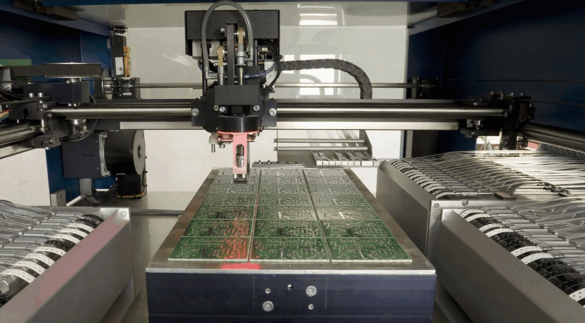
The DFM conversation on an HDI board starts with registration. Every build up layer has to align to the core layers within a tolerance that is a fraction of a typical trace width, and the fabricator needs to know which features are critical. Copper balance across the panel affects both lamination and plating, and the drill programme must be consistent with the aspect ratio limits described earlier.
Panel utilisation drives cost as much as the technology does. HDI panels are processed in small sizes, so a board outline that tiles poorly wastes expensive build up material. The checks and adjustments that a fabricator applies to the digital data before tooling are described in HDI board CAM methods, and reviewing them early avoids the situation where the design is electrically sound but cannot be built as drawn.
Applications and Cost Expectations
Smartphones, wearables, advanced camera modules, automotive radar, server and switch line cards, satellite payloads and 5G infrastructure all use ten layer HDI. The common thread is a requirement for high interconnect density in a small volume, with signal integrity good enough for multi gigabit links or microwave frequencies.
Cost follows the number of build up stages and lamination cycles rather than the layer count alone. Each additional stage adds a drilling and plating operation, more yield risk and more inspection, so a 3+N+3 structure is substantially more expensive than 1+N+1 at the same layer count. Where the density allows it, reducing a build up stage is usually the largest single saving available, and the trade-off should be evaluated before the layout is frozen.
FAQ
What is a 10-layer HDI PCB used for? High density products that need a large pin count in a small outline, including phones, wearables, automotive radar, server and switch boards, satellite payloads and 5G infrastructure.
What limits microvia reliability? The aspect ratio, which should stay near one to one. Deeper holes relative to their diameter produce thin plating at the bottom of the barrel where thermal cycling stress concentrates.
Should microvias be stacked or staggered? Staggered microvias are easier to build and more forgiving of registration error, while stacked microvias save more space but require tighter process control and validation by thermal cycling.