SMT Assembly vs Manual Assembly: Which Should You Use
Almost every production board is assembled by more than one method, and the argument about automation is usually about where the split falls rather than which process is right. SMT assembly places and reflows the fine pitch components that no hand can position reliably, while manual assembly handles the parts that cannot survive an oven, cannot be placed by a nozzle or appear in numbers too small to justify tooling. Understanding where each process is genuinely better keeps cost down without turning the build into an experiment.
Where Each Process Wins
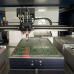
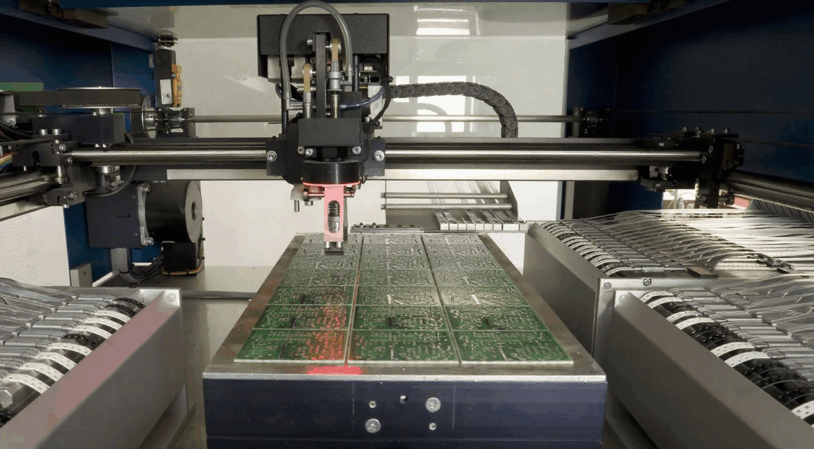
Automated placement wins on repetition. A machine positions components from a feeder at high speed with the same force and the same coordinates every time, which is what fine pitch, small passives and high volume demand. Once the program and the stencil exist, the marginal cost of another board is small and the variation between boards is negligible.
Manual assembly wins on the exceptions. Connectors that must be pressed by hand, parts with leads that need forming, cables that must be dressed into a housing and prototypes with no stencil all belong on a bench. A skilled operator also sees problems that a machine will happily repeat: a mislabelled reel, a reversed polarity mark, a component that does not sit flat.

Placement Accuracy and Component Range
Placement accuracy is measured in fractions of a millimetre on modern equipment, with vision systems correcting for board distortion and component orientation before the part is released. That capability is what makes zero four zero two passives and fine pitch quad flat packs practical at all, and it is matched by a placement force that is controlled well enough not to damage delicate parts.
Hand placement has no comparable repeatability, but it has unlimited reach. Very large components, parts supplied in tubes or trays, and anything that must be positioned against a mechanical reference are easier to handle by hand than to feed into a machine. The practical rule is to automate whatever the machine can place and reserve manual work for the rest.
Reflow, Wave and Selective Soldering
Reflow soldering is the standard for surface mount work and is what gives SMT assembly its throughput. Paste is printed through a stencil, components are placed, and the whole panel passes through a profile that brings the alloy to liquidus and back under controlled heating and cooling. The profile, more than any other variable, decides the quality of the joint and the amount of voiding.
Through-hole parts are handled differently. Wave soldering passes the board over a standing wave of molten alloy, which suits high volume work with many leaded parts, while selective soldering uses a small nozzle or a laser to solder individual joints. Both are compatible with surface mount components already on the board, provided the layout leaves the right clearances and the thermal mass is understood.
Through-Hole and Odd Form Parts
Through-hole components remain common in power supplies, connectors and anything that must survive mechanical load, and they cannot simply be replaced by surface mount equivalents. Automated selective soldering handles many of them, but parts with high thermal mass, awkward geometry or heat sensitive bodies may still need a hand with a controlled iron.
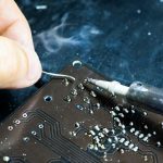
Hand soldering is not a lesser process when it is done properly. A trained operator with a temperature controlled iron, the right tip and a written profile can produce joints that pass the same inspection as a reflowed joint, and the process can be documented well enough to satisfy an auditor. What it cannot do is repeat that result thousands of times without variation.

Volume, Changeover and Tooling
The economics turn on volume and changeover time. A stencil, a program and a feeder setup are worth creating when hundreds of boards will be built, because the setup is amortised across the run. For a handful of prototypes the same setup dominates the cost, and manual assembly with careful documentation is often faster to first article.
Changeover matters as much as volume. Frequent product changes make a machine less attractive unless the feeder setup can be swapped quickly, whereas a bench can switch between jobs with almost no tooling. Where a product family shares a common platform, keeping the same program and stencil across variants keeps the automated route economic at much lower volumes.
Quality Control and Traceability
Both routes need the same inspection discipline. Automated optical inspection is standard after reflow, with X-ray for ball grid arrays and other hidden joints, and in circuit test or functional test downstream. What changes is where defects tend to appear: reflow produces repeatable defects such as insufficient paste or a shifted component, while manual work produces one off errors that vary with the operator and the shift.
Traceability has to cover both. Record the paste lot, the machine program revision, the oven profile and the operator for each stage, because a defect that appears in one batch and not another can usually be traced to a change in one of those. Our notes on PCBA development and in circuit test design show how the test plan fits around the assembly route.
Splitting a Mixed Build
The usual production flow places and reflows all surface mount parts first, then handles through-hole and mechanical parts, then cleans and tests. That order keeps the high temperature step away from parts that cannot take it and allows the stencil to cover only the area it must. Where a part cannot go through reflow at all, it is placed after the oven and soldered by hand or by selective nozzle.
Two practical points decide whether the split works. Keep hand soldered joints away from fine pitch components, since the heat and flux involved are hard to confine. And check that the solder alloy is consistent across both stages, because mixing alloys with different melting points can leave a joint that never fully forms. Our notes on burn in testing cover what happens to those joints under load.
Building the Cost Model
Comparing the two processes on labour rate alone gives the wrong answer. A proper model includes the stencil, the programming and the feeder setup, the machine hour rate, the inspection time, the expected first pass yield and the cost of rework. Manual assembly usually wins on setup and loses on repeatability, and the crossover point moves with component count and package pitch.
It also moves with the number of variants. A product built in ten versions with different component populations pays the setup cost many times, which pushes the balance back toward manual work or toward a flexible line that can change over quickly. Writing the model down, and revisiting it when the volume forecast changes, is more useful than deciding once and applying the answer to every product.
FAQ
Is manual assembly cheaper than SMT assembly? For very small quantities, often yes, because there is no stencil or program to create. Above a few hundred boards the setup cost is amortised and the machine becomes both faster and more consistent.
Can through-hole parts go through reflow? Some can, using pin in paste, where paste is printed into the hole and the part is placed before the oven. It works well for connectors with a compatible thermal mass but requires careful paste volume and hole design.
Which process gives better joints? Both can produce joints that meet the same standard when properly controlled. The difference is repeatability: a reflow profile reproduces the same thermal history on every board, while hand soldering depends on the operator holding a rhythm.