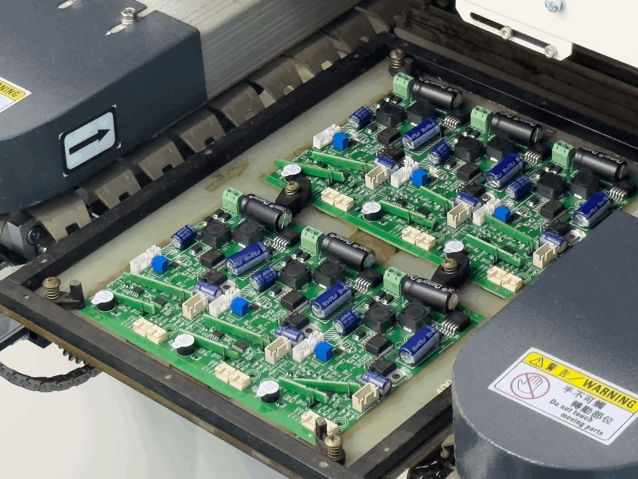
Alarm Panel PCB Design: Zones, Backup Power and Tamper
An alarm panel PCB has to work when everything else has failed. It runs on mains with a standby battery, it monitors a set of loops that may be kilometres of wire, it drives a siren that draws several amperes, and it reports to a monitoring centre over a link that may itself be the first thing an intruder cuts. Every part of the design is shaped by the assumption that the environment will be hostile.
What the Panel Must Do
The panel reads a set of zone inputs, decides whether the state of those inputs is normal, alarming or faulty, drives the notification devices, and communicates with the outside world. It also has to supervise itself: a panel that cannot tell whether its own battery is present, or whether its enclosure has been opened, is not doing its job.
Those requirements make the board an exercise in robustness rather than in speed or density. The signals are slow, the currents are large by circuit board standards, and the operating temperature range is the full one of the installation rather than the comfortable one of an office.
Zone Inputs and Supervised Loops
A conventional zone is a loop of wire with a resistor at the far end, and the panel decides the state from the current that flows through it. A short is an alarm, an open circuit is a fault, and the correct resistance is normal. That arrangement means the panel can detect a cut wire, which a simple contact closure cannot, and it places a requirement on the analogue front end that reads the loop.

The front end has to work over a wide range of loop resistance and capacitance, tolerate a long cable with induced noise, and survive a transient from a nearby lightning strike. In practice the input is protected with series impedance and a clamp, filtered with a time constant that rejects mains hum without missing a fast event, and compared against thresholds that are stable over temperature.
Outputs: Sirens and Relays
The siren output is the most demanding driver on the board. It draws several amperes, it may be several metres of cable away, and its current is interrupted when the siren stops, producing an inductive transient that will destroy an unprotected switch. The output device needs a rating that accommodates the transient as well as the steady current, and the trace has to carry the current with a temperature rise the enclosure can tolerate.
Relay outputs follow the same pattern as any other relay board but with the additional requirement that the polarity of the load and the state of the output must be supervised. A relay contact that has welded closed is invisible to the panel unless it can measure the current or the voltage at the load terminals, and a supervised output is usually worth the extra components.
Standby Power and Charging
The battery is the reason a panel keeps working during a power cut, and battery charging is part of the design. A sealed lead acid battery needs a voltage limited charge, a temperature compensated target voltage if the product is charged across a wide temperature range, and a current limit that does not exceed what the battery can accept.
The board also has to measure the battery. A measurement of terminal voltage under load gives an estimate of the state of charge, and a measurement of the current into and out of the battery gives the rest. The shunt or the sense resistor should be placed where the current path is well defined and where its own voltage drop does not corrupt the measurement. Sizing the copper for the charging current follows the same rules as any other high current path, described in trace width and current calculation.
Communications
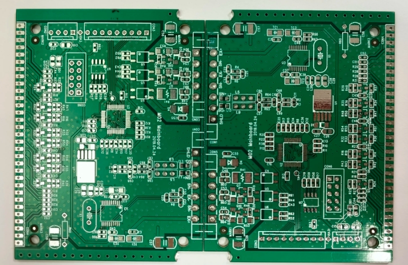
A panel reports over a telephone line, a cellular link, an ethernet connection or all three. The data rates are modest, but the physical layer still has requirements, and the link is exposed because its cable leaves the protected enclosure. Protection at the connector is essential and should be placed so that the transient is diverted before it reaches the transceiver.
A wired data bus, whether it is a proprietary loop or a standard industrial bus, is a differential pair that must be routed with a controlled impedance and a continuous reference if it is to work over a long run with other cables beside it. The routing rules are described in high frequency trace and data bus routing, and a bus that ignores them will work on the bench and fail in the installation.
Tamper, Supervision and Diagnostics
Tamper detection is implemented as a separate switch on the enclosure, monitored by the same input arrangement as a zone but with its own logic. Beyond that, the panel supervises its own supply, its battery, its sounder circuit, its communication path and sometimes its processor, and the results are reported as faults rather than as alarms.
Designing that supervision means providing measurement points on the board that do not interfere with the circuit they measure. A divider across a rail draws current continuously and must be accounted for in the standby budget, and a measurement taken across a switching device has to be filtered so that the pulse width modulation does not appear as a fault.
Layout, Isolation and Surge Protection
The board usually contains mains, a battery, low voltage digital logic and a cable interface that goes outside the building. Those domains have to be separated, with the mains section isolated and its creepage and clearance maintained, and the surge protection placed at the point where each external cable enters the enclosure.
The practical arrangement puts the connectors at one edge, the protection immediately behind them, and the sensitive circuits in the middle of the board where they are furthest from any external connection. The ground structure should give the transient a defined path to the reference and away from the logic, and the mains side should be a distinct region with a visible and measurable boundary.
Testing and Certification
Testing begins with the loops, which should be exercised at the extremes of resistance and capacitance that the installation standard allows, and with the battery, which should be discharged and recharged repeatedly while the panel is monitored. The output circuits are tested with the real siren and with the real cable, because a bench load behaves differently from a long run driving a real device.
Emission and immunity testing follows the product standard, and intrusion equipment is often tested against more severe immunity requirements than consumer electronics, because a false alarm has a cost and a missed alarm has a greater one. The emission limits are met by controlling the return paths of the switching circuits, as described in EMI suppression design principles. Those tests are passed by layout and by protection rather than by filtering alone, and the design should be reviewed against them before the board is committed.
FAQ
Why use a supervised loop instead of a simple contact? Because it distinguishes between a normal state, an alarm and a fault such as a cut cable, which a plain contact cannot do.
How is the battery monitored? By measuring its terminal voltage under load and the current into and out of it, which together give an estimate of the state of charge and of the health of the battery.
Does the panel need surge protection on every cable? On every cable that leaves the enclosure. The protection belongs at the connector so that the transient never reaches the sensitive circuits.