PCB Assembly Carriers and Support Fixture Design
A carrier, sometimes called a pallet or a support fixture, is the piece of tooling that holds a board while a machine works on it. It is easy to treat as the machine supplier’s problem, but the features that make a carrier work are designed into the board, and a board that cannot be supported cannot be assembled reliably.
Why a Board Needs Support
A board with a large area and a small thickness flexes under its own weight when it is held at the edges, and it flexes further when a placement head presses on it. The deflection changes the position of the surface, which affects the accuracy of the placement and the volume of paste that transfers from the pad to the component.
Support is therefore both a mechanical and a process requirement. A board that is supported at enough points behaves as though it were thicker, and the placement accuracy of a fine-pitch part depends on that behaviour as much as on the machine.
Types of Carrier
The simplest carrier is a block with pillars that support the board from below, and it is used on the printer and on the placement machine where the board is flat and accessible from both sides. The pillars are arranged so that they land on areas without components, and the pattern is designed with the board’s layout in hand.
A more elaborate carrier is a frame that holds the board by its edges and carries it through the whole line, including the reflow oven. That type is used for thin boards, for flexible boards and for assemblies that would otherwise not survive the conveyor. Our flexible processing notes describe the related handling constraints.
Designing the Support Pattern
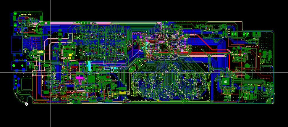
The support pillars must contact the underside of the board without touching a component or a solder joint on the bottom side. On a double-sided assembly, the second pass has components on both faces, so the support has to be arranged around them, and the pattern becomes a layout constraint rather than a machine setting.
That is why a double-sided assembly benefits from planning the second side with the support pattern in mind. Keeping the bottom side free of tall parts in the regions where support is needed avoids a carrier that has to be redesigned for every product.
Carriers for Flexible and Thin Boards
A flexible circuit cannot be placed and reflowed without support, because it will not hold its own shape. The usual method is a rigid carrier with a shallow recess that the flex circuit sits in, held flat by tape or by a vacuum, with apertures cut where components must sit on the underside.
The thermal expansion of the carrier matters here, since the flex material and the carrier expand by different amounts during reflow. A carrier made from a material with a similar expansion keeps the assembly flat, while one that expands differently will pull the circuit out of position.
Fiducials and Carrier Alignment
A board that is held in a carrier is usually located by the carrier rather than by its own edges, so the fiducials that the machine reads must be visible through the carrier or printed on it. Carrier fiducials are more repeatable, because the carrier’s position is set by the machine, while the board’s position within the carrier depends on how well it was loaded.
Both sets are often provided: board fiducials for the placement of fine-pitch components and carrier fiducials for the overall alignment. Our design release checklist lists the fiducial requirements.
Cleaning and Residue
A carrier accumulates flux residue and stray solder over time, and the residue can transfer to the board during handling. Carriers therefore need a cleaning schedule, and the material should be chosen so that it survives the cleaning process without losing its dimensions.
The same applies to any tooling that contacts the board. A fixture that sheds particles onto the surface creates defects that are difficult to trace, because the particle appears on the board rather than at the machine that deposited it.
Depanelisation Fixtures
Where the boards are separated after assembly, the depanelisation step needs its own fixture. A router needs the panel held firmly while the bit cuts, and a scored panel is usually separated in a fixture that applies a controlled bending moment so that the board cracks along the score rather than through the laminate.
The fixture should support the board on both sides of the score line, because unsupported material will bend further than intended and can damage components near the edges. Our breakaway tab notes describe how the separation features are designed.
Cost and Reuse
A carrier is a one-off cost that is amortised across the production run, and its design should be judged against the cost of the defects it prevents. For a fine-pitch assembly the saving is usually immediate; for a simple board with large components the carrier may be unnecessary.
Where a family of products shares a similar outline, a single carrier with interchangeable inserts can serve all of them, which reduces the cost per product and keeps the machine settings consistent across the family.
The practical question at the layout stage is whether the bottom side can be kept clear in the regions where support is needed, and the answer is worth obtaining before the placement is frozen.
Process Control and Verification
Reviewing the design before the data is released is far cheaper than correcting it after the panel is in the tank, because every step downstream inherits the decision made at the front end. Where a value sits close to a process limit, the drawing should say so, since the shop can then open the process window rather than working to a nominal figure that carries no tolerance.
The measurements that matter are the repeatable ones: conductor width and spacing, annular ring, finished hole size, plating thickness and surface finish are all verifiable on a coupon that travels with the panel. Documenting the assumption is part of the design work, and a short note on the drawing prevents a question that would otherwise arrive a day later and cost a day of schedule.
Where a value sits close to a process limit, the drawing should say so, since the shop can then open the process window rather than working to a nominal figure that carries no tolerance. Running a first article through the same checks as the production panel confirms that the two agree, and that comparison is the cheapest form of process control available at prototype stage.
FAQ
Can a board be assembled without a carrier? Yes, where it is thick enough to stay flat under its own weight and the machine can convey it directly. The limit is usually set by the board thickness relative to its area, and a large thin board will need support even if it is a standard thickness.
Does a carrier affect the reflow profile? It does, because the carrier adds thermal mass and shields part of the board from the convection. The profile is normally measured with a thermocouple on the product in its carrier rather than on a bare board, so that the reading reflects what the assembly actually sees.
What does gopcb need to design a carrier? We need the board outline, the thickness, the component positions on both sides, the placement machine’s conveyor dimensions and the location of any parts that must not be touched from below. With those we can propose a support pattern before the assembly is scheduled.