First Article Bring-Up: Mistakes That Cost Days
The first article of a new design is where every assumption in the database meets physics for the first time. Most of the time lost during bring-up is not spent on the design itself but on the small omissions that make a board hard to measure, hard to power up safely and hard to fault find. Those omissions are predictable, and they are cheap to prevent at layout time.
This article collects the mistakes that consume days most often during bring-up, why each of them happens, and what the layout should contain so that the first power-up is a measurement session rather than an investigation.
Test Points And Access
The most common cost of a first article is a measurement that cannot be made. A regulator whose output is only accessible on the far side of a connector, a clock that is only routed between two devices with no accessible node, a ground reference that has to be found by scraping mask: each of these turns a two minute check into an hour of probing.
Adding test points to every power rail, to the clock, to the reset line and to the key interfaces costs nothing in layout terms and a small amount of board area. Where a node is inaccessible, a via with a defined pad size on the bottom layer is often enough, provided the via is placed where a probe can reach it without shorting neighbouring pads.
Power Sequencing And Inrush
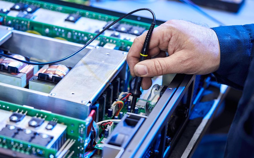
A device with several rails has an order in which they must come up, and the first article is where the order is usually discovered to be wrong. If the sequencing is controlled by enable pins, the resistors that set the delays should be accessible for change. If it is controlled by the natural rise of the supplies, the rise times should be measurable and the loads should be representative.
Inrush current is the other half of the same problem. A large decoupling bank on a low impedance rail can pull a bench supply into current limit at switch-on, which looks like a short circuit until the supply behaviour is understood. Adding a controlled ramp or a current limited start path, and measuring the current rather than guessing, removes an entire class of false diagnosis.
Provisions For Debug
Every design should carry a small number of provisions that are not needed in production but are invaluable on the first article. Series resistors on the bus lines allow a single device to be isolated without cutting a trace. A pull-up or pull-down footprint on a configuration pin allows a mode to be changed. A footprint for an alternative crystal allows a frequency problem to be resolved without a respin.
These provisions cost board area and are usually removed in the next revision, which is the correct outcome. Their value is concentrated in the first weeks, and the cost of leaving them out is paid in the same weeks at a much higher rate. A design that carries none of them is a design that assumes everything is correct, which is a measurement nobody has made yet.
The Interface That Cannot Be Seen
Digital interfaces with no visible activity are the hardest to debug without instrumentation. A bus that is silent may be waiting for a clock, held in reset, configured incorrectly or simply not powered, and the difference between those cases is invisible without a way to observe the lines. Bringing the key interface lines to a header, even if the header is never populated in production, converts an opaque failure into a measurement.
Where the interface runs at a rate that a logic analyser cannot capture reliably, the fallback is to reduce the rate for bring-up. Most controllers allow a slow mode, and starting at the slowest supported rate separates signal integrity problems from configuration problems. Discovering that a link works at one hundred megahertz and fails at one gigahertz is a much more useful result than discovering that it does not work.
Ground And Reference Discipline
Bring-up is where reference problems show themselves as mysterious behaviour. A board with a single ground plane performs well; a board with several planes joined by a narrow bridge can produce measurement artifacts that look like device faults. Checking the continuity and the impedance between the ground points used for the probe and the device being measured is a two minute check that prevents hours of misinterpretation.
The same applies to the oscilloscope connection itself. A probe with a long ground lead sees the loop formed by that lead as part of the measurement, and the ringing it reports belongs to the probe rather than to the circuit. Using the shortest possible ground connection, and confirming the result on a second measurement point, is basic practice that is frequently skipped under schedule pressure.
Process Discipline Around The First Article
A checklist used consistently catches more than experience applied inconsistently. Before power is applied, the supply rails should be checked for shorts, the orientation of every polarised part should be confirmed against the assembly drawing, and the programmed devices should be verified as programmed. After power is applied, rail voltages, current draw and temperature should be recorded before any functional testing begins.
Recording the open loop current at first power is particularly useful, because a board that draws more than the predicted figure has a problem that will appear later as an intermittent fault. The comparison between the measured and the predicted consumption is one of the cheapest diagnostic tests available, and it requires only that a prediction was written down. Following a disciplined design workflow up to release makes that prediction possible.
What The Review Should Have Caught
Most bring-up problems trace back to a review that examined the schematic and the layout separately rather than together. A design review before release that walks the power tree, the clock tree and the reset tree as complete paths will find the missing pull-up, the floating enable and the rail that has no decoupling.
The review should also confirm the measurements that will be needed and the access that has been provided for them. Framing the review around how the board will be tested rather than only how it will be built changes the questions that get asked, and the questions are where the value of the exercise lies. Checking the fabrication package against the order checklist closes the remaining gap between the database and the physical board.
FAQ
How many test points should a board carry? Enough to measure every supply rail, the reset line, the main clock and any interface that cannot be probed elsewhere. In practice that is between ten and thirty points on a moderate design, and the cost is a few square millimetres.
Should the debug provisions be populated on the first article? Only those that are expected to be needed. Unpopulated footprints add no risk, while populated components that are not required add loading and one more variable during diagnosis.
What is the most valuable single measurement on a new board? The current drawn from each rail at first power, compared with the predicted figure. It is available before any code runs, it detects assembly faults as well as design faults, and it costs nothing to make.