Bring-Up Procedure: Design Rules and Process Limits
Bring-up is the process of turning a newly assembled board into a known-good unit, and the difference between a smooth bring-up and a difficult one is almost entirely decided by the layout. The provisions that make it smooth are cheap and they are usually omitted.
Start With Resistance, Not Power
The first measurement on any board is the resistance from each supply rail to ground, taken with the power off. A rail that reads a fraction of an ohm has a short, and applying power converts a repairable fault into a destroyed assembly.
The measurement requires the rail to be separable, which is why a link or a removable component at the source of each rail is worth the board area. Without it the measurement is a resistance in parallel with the rest of the circuitry and is difficult to interpret.
Power Up in Stages
Where the design has several rails, bringing them up in order and checking each one before enabling the next isolates a fault to a single regulator rather than to the whole board. That requires the enable pins to be accessible or to be controlled by a sequence that can be interrupted.
The sequence also protects the devices. A processor that is powered before its interface logic can be damaged by the current that flows through the protection diodes, which is why the sequence is a requirement rather than a convenience. Our interface layout notes describe the related requirements.
Current, Not Just Voltage
A rail at the correct voltage may be drawing far more current than expected, and the excess is often the first sign of a fault that has not yet failed. Measuring the current at the link for each rail gives that information early.
The expected current should be written into the bring-up procedure before the board is built, so that the measurement is a comparison rather than an observation. The difference between the expected and the measured value is the useful quantity.
Clock, Reset and Configuration
A processor that does not execute usually lacks a clock, is held in reset, or is configured to boot from a source that is not present. The three conditions are indistinguishable without access to the relevant signals.
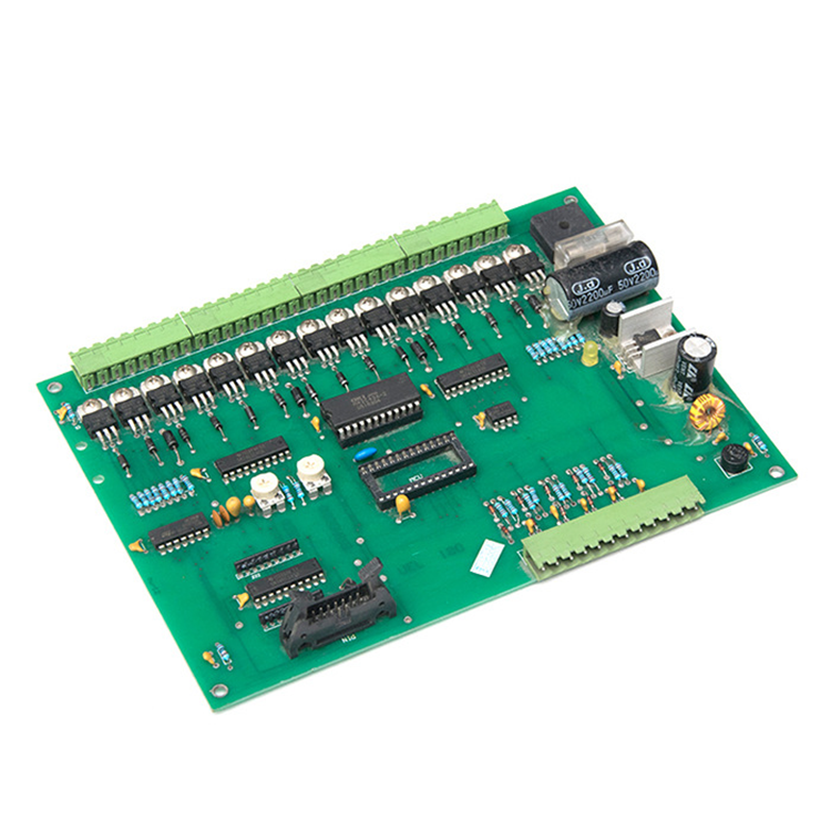
Access means a test point on the clock and on the reset line, and a predictable state on the boot configuration pins. Where the configuration is set by resistors, a header that allows the state to be changed is a small addition with a large benefit.
<img src="https://www.gopcba.com/wp-content/uploads/2026/09/63.jpeg" alt="Debug header and test points on an assembled PCB” />
The Debug Interface
The debug interface is what turns a failure into an explanation, and it has to be accessible after assembly. A header that is covered by a shield or blocked by a connector will be used once and then left disconnected.
Where the design is too small for a header, a footprint for a pogo-pin adapter is the alternative, and the pads should be placed clear of tall components so that the adapter can seat.
Provisions for Expected Modifications
Every design has a short list of modifications that experience suggests are likely, and providing footprints for them costs almost nothing. The classic candidates are a pull-up on a signal that floats, a capacitor on a node that rings, and a resistor that sets a current.
The value appears when the modification is needed. Fitting a component to an existing footprint takes a minute; cutting a trace and adding a wire takes an hour and introduces a risk of damage.
Documenting the Expected Results
The bring-up procedure should state what each measurement is expected to be, within a range. A procedure that says only what to measure produces a set of numbers with no way to tell whether they are correct.
The expected values come from the design calculations and from the datasheets, and writing them down is part of the design work rather than part of the test work.
Recording the Actual Results
The measured values from the first board are the reference for every later board, and they should be recorded against the serial number. A board that measures differently from the first one is a board with a problem, even if both are within specification.
The record also accumulates into a baseline for the design. Where a later revision changes a value, the comparison is immediate. Our design release checklist lists the provisions that make the record possible.
Additional Considerations for This Build
Practical attention to rail link pays for itself here, because it decides whether the finished board behaves as the drawing intended. Where the requirement is not stated on the fabrication drawing or in the assembly notes, the shop has to assume a default, and that default is rarely the value the design was simulated with. Stating rail link explicitly, together with the tolerance that applies, removes the assumption and keeps the result predictable from batch to batch.
Process Control and Verification
On a design of this kind, rail link is the item that decides how the rest of the board is arranged. The process window is set by the narrowest step in the flow, so an improvement anywhere else shows up as margin rather than as yield until that step is addressed. A short note on the drawing about handling, storage or packaging is often worth more than an extra decimal place on a tolerance.
Where a value sits close to a process limit, the drawing should say so, since the shop can then open the process window rather than working to a nominal figure that carries no tolerance. A stack-up that is drawn rather than described removes most of the ambiguity from a quotation, and it lets the fabricator price the board against the dielectric and copper weights that will actually be used.
Where the requirement is not written down, the shop supplies its own default, and the default is chosen for the process rather than for the design.
Related reading: our fabrication notes, board quality and design release notes cover the same ground.
Process Control and Verification
On a design of this kind, rail link is the item that decides how the rest of the board is arranged. The process window is set by the narrowest step in the flow, so an improvement anywhere else shows up as margin rather than as yield until that step is addressed. A short note on the drawing about handling, storage or packaging is often worth more than an extra decimal place on a tolerance.
FAQ
Is a bring-up procedure necessary for a small board? It is more valuable on a small board, because the options for improvisation are fewer. The procedure can be short, but it should exist before the first board is powered.
What if the rail cannot be separated? The resistance measurement can still be made by comparing the reading with the expected parallel resistance, and the current can be estimated from the supply’s behaviour. Neither is as clear as a link, which is why the link is worth providing.
What does gopcb provide for bring-up? We provide a board that matches the drawing, a record of the first article measurements, and where requested the coupon data for impedance and plating. We also report any deviation found during the build rather than after the board is powered.