Solder Ball and Bump Height Control in BGA Assembly
Solder ball geometry is one of the most closely watched characteristics in modern BGA assembly. Every ball has to carry the right volume, sit at the right height, and hold a narrow window from reflow through final test. When bump height drifts, joints open, bridges form, and yield falls. This guide explains how gopcb controls ball formation, paste volume, reflow profile and measurement so that bump height stays inside the process window.
Why Bump Height Defines Joint Reliability
Every solder ball in a BGA array is a mechanical joint and an electrical connection at the same time. Height variation changes the stress that each joint carries, and the tallest ball in the array can hold a package away from the remaining joints. Once a ball fails to collapse into contact with its pad, the joint becomes a latent open circuit that no functional test may catch.
Height also drives assembly yield. A ball that is too tall displaces neighbouring joints, while a ball that is too short starves the fillet and weakens the connection. Both conditions shorten the fatigue life of the whole interconnect. Designers therefore treat bump height as a controlled characteristic rather than an inspection detail, and they set limits from reliability data instead of visual appearance.
Solder Ball Formation from Paste to Sphere
Most solder ball arrays begin as printed or jetted paste deposits that melt and pull into spheres during reflow. Surface tension does the shaping, so the final height depends mainly on deposited volume and pad geometry. When paste volume is stable and the pad is round, clean and properly finished, the sphere forms predictably. Any change in aperture size, paste rheology or pad finish shifts the result.
Pre-formed balls are placed instead of printed paste when the pitch is very fine or the required deposit is too small to print. Placement accuracy then dominates, because an off-centre ball collapses asymmetrically and ends up shorter on one side. Our notes on BGA reballing explain how the same mechanics apply during rework, and why replacement ball size and alloy must match the original sphere.

Bump Height Targets and Tolerance Windows
A target bump height only means something when it is paired with a tolerance. Typical windows are written as a nominal height plus or minus a few micrometres, measured across the array and across panels. The window must be wide enough to run economically and narrow enough to protect the joint. Teams derive it from the collapse behaviour of the alloy, the standoff of the package, and reliability testing of that specific stack-up.
Two numbers matter: the mean and the spread. A process can sit exactly on target and still fail, because the tails of the distribution fall outside the window when the standard deviation is large. Reporting both values, together with a capability index, turns bump height into a process metric instead of a pass or fail inspection result that nobody can act on.
Paste Volume and Aperture Design Effects
Paste volume is the largest single lever on bump height in a printed process. Aperture area, stencil thickness and the area ratio of the opening decide how much material releases onto the pad. As apertures shrink below the recommended area ratio, transfer efficiency drops and deposits become inconsistent. Fine pitch work therefore needs thinner stencils, better paste and tighter squeegee control. Our paste inspection guide covers how deposit volume is measured in practice.
Aperture shape and wall quality matter too. Laser cut walls with rough edges hold paste back, while electroformed or polished walls release more cleanly. The link between print quality and downstream results is close enough that print inspection belongs in the same control loop as ball measurement. When deposits drift, ball height follows within a few panels.
Reflow Profile Control for Ball Geometry
The reflow profile decides how completely the deposit melts, how long it stays liquid, and how far it spreads before solidifying. A soak that is too short leaves cold joints and irregular spheres, while excessive time above liquidus drives oxidation and intermetallic growth. Ramp rate matters as well, because a fast ramp volatilises flux unevenly and can eject material from the joint.
One profile does not fit a whole product. Large copper planes, heavy connectors and thin packages absorb heat at different rates, so the profile must be measured on the real assembly with thermocouples. Once it is locked, changes in oven condition, belt speed or ambient temperature have to be monitored before they alter ball geometry.
Coplanarity and Warpage Interactions
Coplanarity describes how flat the ball array is relative to a reference plane. Package warpage and board warpage both feed into the picture, and their directions do not always match. When a package bows away from the board, edge balls may not touch the paste at all. When it bows toward the board, centre balls are over-compressed. Both outcomes change the heights that reflow produces.
Warpage depends on material, layer construction and moisture content. Popcorn damage from absorbed moisture is the most dramatic cause, but gradual bow from asymmetric copper distribution is far more common. Storage, baking and panel design all influence the final shape, so coplanarity is managed upstream as much as it is measured at assembly.
Collapse Behaviour and Final Standoff
During reflow the ball partially collapses under the weight of the package, and the final standoff balances gravity, surface tension and the solid solder balls that hold the corners. Alloys with a narrow melting range behave differently from those with a wide pasty range, and the difference shows up directly in standoff. Choosing an alloy without checking its collapse behaviour is a common source of height variation.
Stiff packages with a high ball count collapse less than small, light devices. That is why the same alloy can hit the height target on one package and drift on another. Validating each package and alloy combination with a first article build removes that uncertainty before volume production starts and before scrap is generated.
Inspection and Measurement Methods
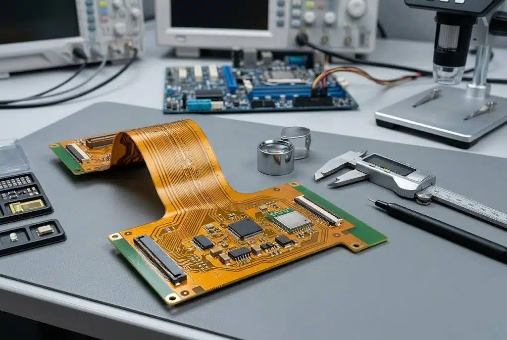
Height is measured optically, or with shadow based systems that compare ball tops against a reference plane. These tools report coplanarity, missing balls and extra balls in a single pass. X-ray adds the ability to see the joint beneath the package, which is essential once collapse has already occurred. Our comparison of X-ray and AOI shows where each method is strongest.
The measurement itself has to be trustworthy. Reference planes drift, calibration expires, and software thresholds can be set so loosely that real defects pass. Gauge studies confirm that the system resolves differences smaller than the tolerance window being controlled, and daily verification against a known sample keeps the results honest over months of production.
Feeding Data Back into Process Control
Bump height data is only useful when it closes the loop. Measurements should be tied to panel, printer, oven and time, so that a shift can be traced back to the machine that produced it. Print data belongs in the same traceability chain, which is why paste inspection and ball measurement should be reviewed together during process audits.
Once the loop exists, teams correct the process before scrap accumulates. Trends are obvious in control charts, and a slow drift in mean ball height usually appears in paste volume first. At gopcb that sequence points to the printer rather than to sorting, which keeps the defects described in common solder failures rare instead of routine.
FAQ
What bump height tolerance is normal? Tolerances are set per package and alloy, and typical windows are only a few micrometres wide around the nominal value. The right number comes from collapse testing and reliability data for that stack-up, not from a generic table. A window that is too tight rejects good product, and one that is too wide ships latent opens to the customer.
Does paste volume or the reflow profile matter more? Paste volume sets the height that is possible, and the reflow profile decides how much of that potential becomes a stable sphere. Both must be controlled, but paste volume is usually corrected first because it drifts earlier and is easier to measure on every panel that passes the printer.
How often should bump height be measured? Sampling should be frequent enough to catch a shift before a whole panel is scrapped, so most lines measure at the start of every build, after each paste lot change, and at fixed intervals during production. Any change to the printer, stencil or oven triggers an immediate check.