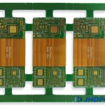
Designing FPC Display Cables for Handheld Products
A display cable inside a handheld product is one of the most constrained pieces of interconnect in the device. It has to fit into a gap a few millimetres wide, fold twice on its way from the main board to the panel, carry a high speed differential pair and a handful of power rails, and survive being dropped. It is also usually the last part of the design to be frozen and the first to be blamed when a unit fails.
Getting an FPC display cable right comes down to a small number of decisions made early: how many layers, which material, where the bends fall, how the shield is terminated and what happens at the connector. Each of them is cheap to change in the first layout and expensive to change afterwards.
Layer Count and Material Choice
A single sided flex is the cheapest option and is adequate when the signal count is low and no controlled impedance is needed. As soon as a differential pair has to be referenced to a plane, a two layer construction with a ground plane on the opposite side becomes necessary. Beyond that, the limiting factor is usually not the signal count but the need for shielding and for a return path that does not share the ground of the noisy digital section.
Base material is almost always polyimide for a flex cable, with rolled annealed copper rather than electrodeposited foil. Rolled copper has a grain structure that tolerates repeated bending far better, and the difference shows up in the number of flex cycles the cable survives rather than in any electrical parameter. Where the cable also has to handle a high speed pair, the dielectric properties of the adhesive system between the copper and the polyimide coverlay become part of the loss budget.

Bend Radius and Neutral Axis
The copper in a flex cable fails by fatigue when it is repeatedly stretched and compressed. The strain it sees depends on how far it sits from the neutral axis of the stack and on the radius of the bend. A symmetric construction places the conductors in the middle of the stack, roughly on the neutral axis, which reduces the strain for a given radius. An asymmetric stack does the opposite, and it is one of the most common reasons a cable cracks after a few thousand folding cycles.
Practical rules follow from that. A static bend should have a radius of at least ten times the total thickness, and a dynamic one at least one hundred times. The bend line should be placed away from plated holes, from the connector and from any stiffener, because each of those is a discontinuity where the strain concentrates. Where a fold must be tight, a coverlay opening that thins the stack locally, sometimes called a bend relief, allows a smaller radius without exceeding the copper strain limit.
Shielding and Impedance Control
A display cable runs next to an antenna, a camera module and a switching regulator, so it is both a victim and a source of interference. A cross hatched ground plane on the opposite layer reduces radiated coupling, and a full ground plane with a defined reference gives a controlled impedance for the differential pair. The decision depends on the frequency content of the signals and on the emission limits the product has to meet.
One aspect that surprises designers is the return path. At the connector, the ground pins of the flex must be tied to the ground of the main board with a low inductance path, and there should be enough of them. A single ground pin in a fine pitch connector adds enough inductance to spoil the impedance match of a pair that was carefully designed along the length of the cable, an effect that belongs to the same family as any impedance discontinuity.

Connector and Termination Design
The cable tail that plugs into the connector needs a stiffener, usually a polyimide or FR4 layer bonded behind the contacts, so that the contacts can be inserted without the tail flexing. The stiffener defines the insertion depth as well as the stiffness, and its thickness has to be matched to the connector geometry; too thin and the contacts do not seat, too thick and the tail will not enter.
Where the cable is soldered to the board rather than plugged in, the pads should be as large as the pitch allows and the solder joint should be supported by an adhesive fillet or a bonded stiffener. Hot bar soldering and anisotropic film bonding are both used at this interface, and the choice affects the pad geometry as well as the process. A cable that is soldered at both ends also has to survive the reflow profile of the assembly, which sets a limit on the adhesive system used in the flex.
Assembly, Handling and Test
Flex cables are damaged by handling far more often than by any electrical stress. A cable that is pulled by the tail rather than by the body, or folded back on itself during test, may pass the functional test and fail later. Design measures that help include leaving a service loop, keeping the bend lines visible in the drawing, and specifying a pull tab or a handling tab that is removed after assembly.
Testing should include a continuity and resistance check on every conductor, a hi pot test between adjacent conductors if the application requires it, and a visual check of the bend area under magnification after the cable has been folded into its final position. Where the product is expected to be opened for repair, the cable should be specified for a defined number of reconnections, since the connector contacts and not the copper are usually what wears out. All of these requirements belong in the same document that defines the cable assembly build.
Additional Considerations for This Build
Practical attention to shield termination pays for itself here, because it decides whether the finished board behaves as the drawing intended. Where the requirement is not stated on the fabrication drawing or in the assembly notes, the shop has to assume a default, and that default is rarely the value the design was simulated with. Stating shield termination explicitly, together with the tolerance that applies, removes the assumption and keeps the result predictable from batch to batch.
Process Control and Verification
On a design of this kind, shield termination is the item that decides how the rest of the board is arranged. Where the requirement is not written down, the shop supplies its own default, and the default is chosen for the process rather than for the design. The measurements that matter are the repeatable ones: conductor width and spacing, annular ring, finished hole size, plating thickness and surface finish are all verifiable on a coupon that travels with the panel.
Related reading: our fabrication notes, board quality and design release notes cover the same ground.
Power and Ground Distribution in a Narrow Cable
A display cable usually carries a backlight supply, several logic rails and the ground return for all of them. Because the cable is narrow, the copper available for those rails is limited, and the voltage drop along a thin trace can be enough to shift the panel brightness or to trip an undervoltage detector. Calculating the trace width from the current and the allowable drop, rather than from the minimum width the fabricator can etch, is the first step.
The return current deserves as much attention as the supply. If the ground conductors are narrow, the return path has a high impedance, and the voltage developed across it appears as noise on every signal that references it. Wide ground traces on both sides of the cable, stitched together where the construction allows, lower that impedance and also reduce the loop area that radiates. The same reasoning that applies to trace width and current on a rigid board applies here with less copper to work with.
FAQ
Can a display cable use ordinary FR4 instead of polyimide? Only for a static bend inside a rigid flex construction. FR4 has poor flex fatigue life and will crack at a bend that a polyimide cable survives indefinitely.
Is shielding always necessary? Not always. If the cable carries differential signals with a return path on the same flex and the emission margin is comfortable, a cross hatched return may be enough. A shield adds thickness and stiffness, which in turn affects the bend radius.
How many flex cycles should be specified? The number should come from the product usage model, with margin. A cable that folds once during assembly and never again is a different specification from one that folds every time a lid closes.