Board Level Vibration Testing: Setup, Resonance and Failure
A board that survives a drop in the laboratory sometimes fails in the field, and one that fails on a shaker sometimes survives a lifetime of service. The reason is that vibration testing measures the response of a system, and the system includes the fixture, which is rarely the same as the enclosure.
What the Test Measures
A vibration test applies a controlled motion to the board and measures either the resulting deflection or the electrical continuity of daisy chained joints. The first approach characterises the mechanics, and the second detects the failure.
The motion is specified as a profile of frequency against acceleration, and the test either sweeps through the range or dwells at particular frequencies. A sweep finds the resonances, and a dwell proves the fatigue life at the worst one.
The two are complementary. A sweep alone shows where the board is weak, and a dwell alone tests a frequency that may not be the worst case.
Finding the Resonances
A sine sweep from low frequency upward with a constant input acceleration shows the frequencies at which the response peaks. The first mode is usually the board flexing between its fixings, and the higher modes involve the board twisting or the components moving on their leads.
Where a component resonates at a frequency the board also amplifies, the stress on its leads is multiplied by the board response. This is the mechanism behind a component failing on a board that passes the same test without it.
A small accelerometer placed on the board itself, rather than on the fixture, is what makes the measurement meaningful. A measurement made on the fixture describes the input and not the response.
Fixturing the Board
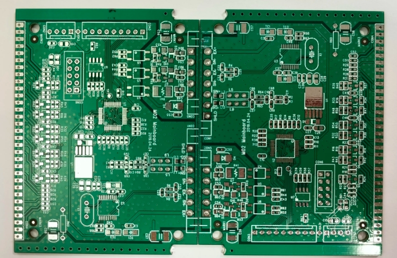
The board must be fixed in a way that represents its installed condition. Pinning it at every mounting hole reproduces the real boundary condition; clamping it along the edges does not, and it usually makes the board stiffer than it is in the product.
A fixture that is too flexible adds a mode of its own, which can appear at a frequency that is mistaken for a board resonance. The fixture should be stiff enough that its first mode is well above the range of interest.
The screws and washers should be the ones used in the product, since the clamping stiffness affects the boundary condition at each hole. Our board outline notes describe how the fixing positions relate to the outline.
Daisy Chains and Failure Detection
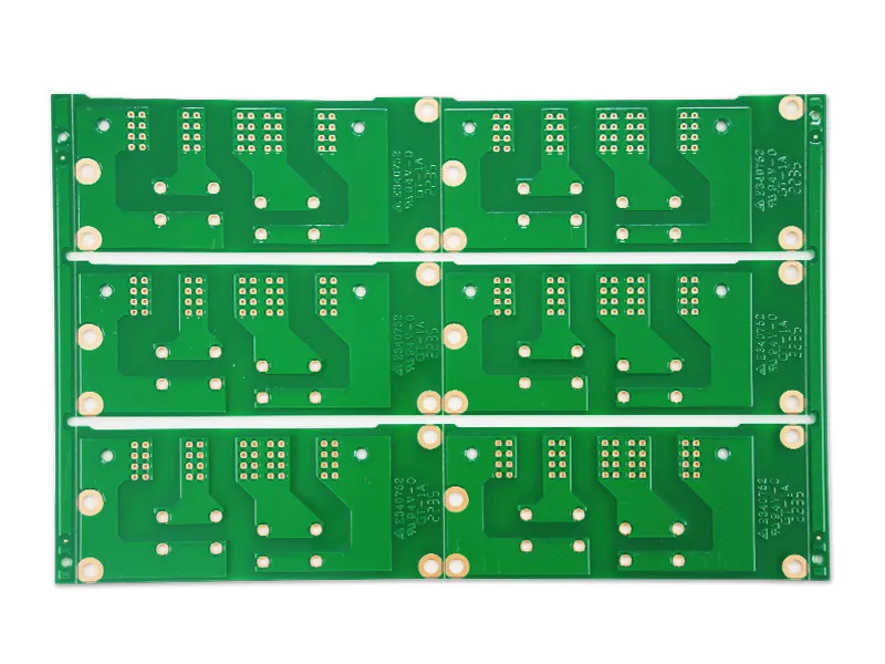
A daisy chain routes the joints of interest in series so that a crack in any one of them appears as an increase in resistance. The chain is monitored continuously during the test, and the time of the first event is the result.
The chain must be designed on the board, and building it after the fact is not possible. Our coupon notes describe how such structures are laid out so that the failure is located as well as detected.
The detection threshold matters. A threshold that is too high misses the early events that consume the life of the joint, and one that is too low records noise as a failure. The threshold should be stated with the result.
Random Vibration and the Real Environment
Real vibration is broadband and random rather than a clean sine wave. Random vibration is specified as a power spectral density, and the test applies energy across a range of frequencies simultaneously.
Random testing excites all the modes at once, which is closer to a transport or engine environment, and it produces a stress history that can be converted into a fatigue estimate.
The equivalence between sine and random testing is not straightforward, and a result from one should not be quoted as evidence for the other. Our component reliability notes describe how the stress is related to the joint life.
Shock and Drop
A shock test applies a high acceleration for a few milliseconds, which is the condition produced by a drop or by a handling impact. The failure modes differ from vibration: a shock produces a single large stress that can crack a joint or a component body immediately.
Drop testing of a product is performed on the assembled unit, and the board level test uses the same pulse applied to a fixture. The board level test is more repeatable and less expensive, and it does not reproduce the enclosure’s effect.
The pulse shape and duration define the test. A shorter pulse at the same peak acceleration contains less energy and produces a different response, so the specification must include the duration.
Interpreting a Failure
The location of the failure is the useful information. A crack at the corner joint of a large package indicates thermal or bending stress, a crack at the lead of a heavy component indicates vibration, and a crack at a connector indicates a load applied by a cable.
The number of cycles to failure is compared against the requirement, and a result that is marginal is treated as a design change rather than as a pass with a warning.
Sections of the failed joint, taken along the crack, identify whether the failure started at the interface or in the bulk of the solder. Our quality notes describe the sectioning and measurement.
Making the Test Useful
The test is useful when the boundary conditions, the input profile, the instrumentation and the failure criterion are all recorded. Without them the result cannot be compared with another test or repeated.
Testing the worst case configuration, with the heaviest components and the most flexible board, gives the most information. Testing a convenient sample gives a result that applies only to that sample.
Repeating the test after a design change is what turns it into evidence. A single test is a snapshot, while a series across revisions shows which change fixed the problem.
Process Control and Verification
On a design of this kind, vibration test is the item that decides how the rest of the board is arranged. A stack-up that is drawn rather than described removes most of the ambiguity from a quotation, and it lets the fabricator price the board against the dielectric and copper weights that will actually be used. Where the requirement is not written down, the shop supplies its own default, and the default is chosen for the process rather than for the design.
Process Control and Verification
On a design of this kind, vibration test is the item that decides how the rest of the board is arranged. A stack-up that is drawn rather than described removes most of the ambiguity from a quotation, and it lets the fabricator price the board against the dielectric and copper weights that will actually be used. Where the requirement is not written down, the shop supplies its own default, and the default is chosen for the process rather than for the design.
FAQ
How long should a vibration test run? Long enough that the first failure events appear, and long enough to demonstrate margin. A test that ends before the first event has shown nothing.
Does passing a board level test guarantee the product passes? No. The enclosure changes the boundary conditions and may add or remove resonances, so the product level test remains the final evidence.
What does gopcb provide for vibration testing? We provide coupons with daisy chained joints for the components of interest, fixtures that reproduce the installed boundary conditions, sine and random profiles with continuous resistance monitoring, sectioning of the failed joints, and a comparison across design revisions. Where a design has no margin, the test identifies the component that needs attention rather than only reporting a failure.