BGA Warpage and Coplanarity in Reflow
A ball grid array is soldered by joints the inspector cannot see, and the failure that matters most is a joint that never formed because the package and the board were not parallel when the solder was molten.
Warpage in a Package
A package is a sandwich of materials with different expansion coefficients, and its shape changes with temperature. At room temperature it may be flat or slightly bowed, and at reflow temperature the bow can reverse.
The characteristic behaviour of a plastic ball grid array is a smile at room temperature and a frown at reflow temperature, because the substrate and the mould compound expand at different rates.
The magnitude depends on the package size, the thickness of the substrate and the moisture content. A package that has absorbed moisture warps more, which is one reason the moisture sensitivity level matters even when there is no popcorning.
Warpage in the Board
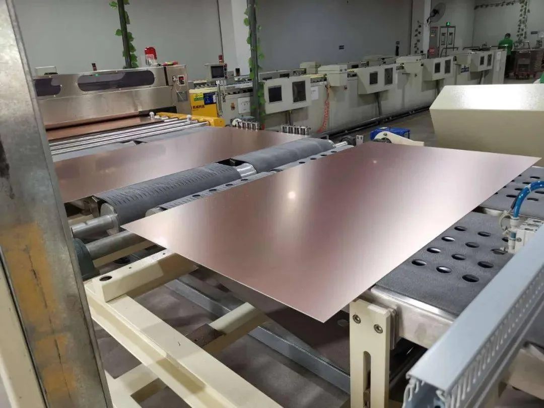
The board also changes shape, driven by its own copper distribution and by the temperature gradient through the oven. A board with copper on one side only will bow toward the copper at reflow.
Panel level warpage and unit level warpage differ, because the panel constrains the unit until it is separated. A design that is flat as a panel can bow after depaneling.
The board’s contribution can be reduced by balancing the copper across the stack and by keeping large copper areas away from the area directly under the package. Our thermal design notes describe how the copper is distributed.
How the Two Add Together
The gap at a joint during reflow is the sum of the package warpage, the board warpage and the solder paste height. Where the sum is negative at the corner of the package, the ball is pressed into the paste and the joint forms with an excess; where the sum is large, the ball does not reach the paste.
The critical location is the corner of the package, which is where the warpage is largest and where the ball is furthest from the neutral point.
An open joint at a corner ball is the classical signature of a warpage problem, and it appears on a package that passed every incoming inspection. Our inspection notes describe how to find it.
Detecting the Condition
X-ray inspection finds an open joint where the ball is separated from the pad, and it finds a joint with excessive solder where the ball was pressed. The image must be taken at the right angle to see the separation.
Coplanarity of the package can be measured before assembly, and the measurement at reflow temperature is the one that matters. Some suppliers provide the data; the rest can be measured in a laboratory with a shadow moire or a similar system.
The board warpage can be measured the same way, and the sum compared against the available paste height. This is the calculation that predicts whether the assembly will work before the boards are built. Our quality notes describe the measurements taken on the panel.
Process Measures
The paste volume is the margin in the system. Increasing it allows a larger gap to be bridged, at the cost of a higher risk of bridging between adjacent balls.
The reflow profile controls the temperature at which the package warps. A slower ramp and a longer soak allow the package to reach a more uniform temperature and reduce the gradient driven warp.
A support fixture that holds the board flat during reflow removes the board contribution and is sometimes the cheapest fix. The fixture must be designed for the profile and must not shadow the board from the convection. Our solder defects notes describe the resulting joint appearance.
Design Measures
Choosing a package with a thicker substrate or a different construction reduces the warpage but is usually not under the designer’s control.
What the designer controls is the copper under and around the package. Keeping the copper balanced and avoiding a large plane directly beneath the package centre reduces the differential movement.
Where the design allows, placing the package on a thinner board reduces the board’s stiffness and lets it conform to the package rather than fighting it. This is a counterintuitive measure that is sometimes the right one.
Verifying After Assembly
The verification is an X-ray inspection of the corner balls on the first article, followed by a destructive inspection or a cross section where the X-ray is ambiguous.
A thermal cycling test on the assembly then shows whether the marginal joints survive. A joint that formed with insufficient solder may pass the electrical test and fail after a few hundred cycles.
Our component reliability notes describe how the joint life is estimated from the thermal excursion, which is the input to the decision about whether the marginal joint is acceptable.
Process Control and Verification
On a design of this kind, coplanarity is the item that decides how the rest of the board is arranged. The process window is set by the narrowest step in the flow, so an improvement anywhere else shows up as margin rather than as yield until that step is addressed. A short note on the drawing about handling, storage or packaging is often worth more than an extra decimal place on a tolerance.
Where a value sits close to a process limit, the drawing should say so, since the shop can then open the process window rather than working to a nominal figure that carries no tolerance. A stack-up that is drawn rather than described removes most of the ambiguity from a quotation, and it lets the fabricator price the board against the dielectric and copper weights that will actually be used.
Where the requirement is not written down, the shop supplies its own default, and the default is chosen for the process rather than for the design.
Process Control and Verification
On a design of this kind, coplanarity is the item that decides how the rest of the board is arranged. The process window is set by the narrowest step in the flow, so an improvement anywhere else shows up as margin rather than as yield until that step is addressed. A short note on the drawing about handling, storage or packaging is often worth more than an extra decimal place on a tolerance.
Where a value sits close to a process limit, the drawing should say so, since the shop can then open the process window rather than working to a nominal figure that carries no tolerance.
Process Control and Verification
On a design of this kind, coplanarity is the item that decides how the rest of the board is arranged. The process window is set by the narrowest step in the flow, so an improvement anywhere else shows up as margin rather than as yield until that step is addressed. A short note on the drawing about handling, storage or packaging is often worth more than an extra decimal place on a tolerance.
FAQ
Does baking reduce warpage? Baking removes moisture, which reduces the amount by which the package warps at temperature. It does not change the fundamental construction.
Can a warped package be straightened? No. The selection has to be made at the supplier and the design has to accommodate the behaviour.
What does gopcb provide for warpage sensitive packages? We provide warpage measurements at temperature for the package and the board, a paste volume recommendation based on the sum, profile development that minimises the gradient, support fixtures where the board contribution is significant, and X-ray verification of the corner joints.