
In-System Programming in Production: Setup and Control
A board that leaves the assembly line without firmware is not a product. Programming has become part of the assembly process, and it introduces its own requirements on the layout, the test and the traceability.
Where Programming Fits
Programming can be performed before assembly, on the bare device, after assembly but before test, or as part of the functional test. Each position has different requirements.
Programming before assembly requires the devices to be handled individually, which is practical for a small number of parts and impractical for volume. It also means the firmware is fixed before the board exists.
Programming after assembly uses the in-system programming interface, which is the usual method for volume production because it allows the firmware to be loaded on the finished assembly and updated later. Our design release checklist notes where the programming requirement is recorded.
What the Layout Must Provide
The programming interface needs access to the programming pins, a ground and a power supply. The pins may be shared with other functions, in which case the circuit must tolerate the programming signals.
The access should be through test points or a connector that the fixture or the programmer can reach. Where the interface is used in production and in the field, the same access serves both, which is why a debug connector is often retained on the product.
The signal integrity of the programming lines matters for the programming speed. A long trace with poor return path slows the programming and can cause intermittent failures that look like firmware problems. Our fabrication notes describe how the access is documented.
Programming During Test
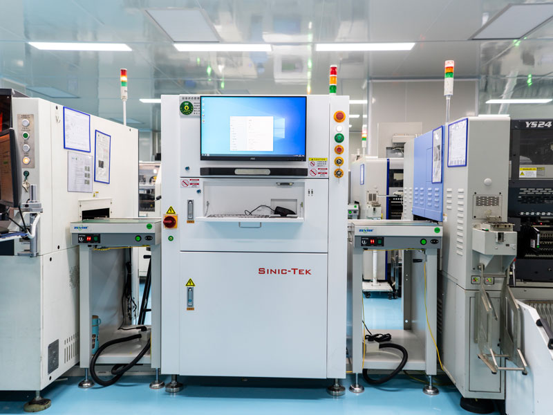
Programming within the functional test uses the same fixture and the same connection, which saves time and avoids a separate handling operation. The test program performs the programming and then runs the functional checks.
The programming time counts towards the test time, and a large image over a slow interface can dominate the cycle. The interface speed is therefore a production parameter and not only a design detail.
Where the test fixture cannot reach the interface, a separate programming station is needed, which adds a handling operation and a queue. Our inspection notes describe how the programming step is sequenced with the inspection steps.
Version Control and Traceability
The firmware version loaded on each unit must be recorded, because a field failure may depend on the version and because a recall must identify which units are affected.
The record should link the unit’s serial number or its board identifier to the firmware version and the programming date. This is the same requirement as for a component lot and it is handled by the same system.
A unit that is reprogrammed during rework should have the new version recorded rather than the old one overwritten, so that the history is complete. Our industrial assembly notes describe the data structure used.
Security and Access
An accessible programming interface is also a way into the product. Where the product must be protected, the interface is disabled after programming or protected by a key.
The protection must not prevent legitimate field updates. The design should therefore distinguish between a production interface and a field update mechanism, which may be the same port with different authentication.
The production data, including any keys or calibration values, must be handled so that it does not become a source of clones. This is a process requirement as much as a technical one.
Preventing Wrong Firmware
The commonest programming defect is the wrong image loaded on the board. A board that runs the firmware for a different product may pass a functional test designed loosely and fail in the field.
The protection is to have the test verify the version after programming and to compare it against the expected value for the product being built. The verification is part of the test record.
Where the same physical board is used for several products, the check becomes essential, because nothing about the hardware distinguishes them. Our solder defects notes describe the failure modes that appear when a unit carries firmware for another product.
Programming Failure Modes
A programming failure can be caused by the device, by the interface, by the power supply or by the fixture. Distinguishing them requires the error to be reported rather than only the pass or fail.
The supply voltage during programming must be within the device specification. A marginal supply produces intermittent failures that appear as random programming errors.
The fixture contact resistance affects the programming interface and a marginal contact produces errors that move between units. Our quality notes describe how the failures are classified.
Process Control and Verification
On a design of this kind, version control is the item that decides how the rest of the board is arranged. A short note on the drawing about handling, storage or packaging is often worth more than an extra decimal place on a tolerance. Where a value sits close to a process limit, the drawing should say so, since the shop can then open the process window rather than working to a nominal figure that carries no tolerance.
A stack-up that is drawn rather than described removes most of the ambiguity from a quotation, and it lets the fabricator price the board against the dielectric and copper weights that will actually be used. Where the requirement is not written down, the shop supplies its own default, and the default is chosen for the process rather than for the design.
The measurements that matter are the repeatable ones: conductor width and spacing, annular ring, finished hole size, plating thickness and surface finish are all verifiable on a coupon that travels with the panel.
Process Control and Verification
On a design of this kind, version control is the item that decides how the rest of the board is arranged. A short note on the drawing about handling, storage or packaging is often worth more than an extra decimal place on a tolerance. Where a value sits close to a process limit, the drawing should say so, since the shop can then open the process window rather than working to a nominal figure that carries no tolerance.
A stack-up that is drawn rather than described removes most of the ambiguity from a quotation, and it lets the fabricator price the board against the dielectric and copper weights that will actually be used.
Process Control and Verification
On a design of this kind, version control is the item that decides how the rest of the board is arranged. A short note on the drawing about handling, storage or packaging is often worth more than an extra decimal place on a tolerance. Where a value sits close to a process limit, the drawing should say so, since the shop can then open the process window rather than working to a nominal figure that carries no tolerance.
FAQ
Can a board be programmed before assembly? It can, and it requires the firmware to be final and the parts to be handled individually. It is used where the programming interface is not accessible after assembly.
Should the programming interface remain on the product? Where field updates are expected, yes. Where they are not, disabling it reduces the attack surface.
What does gopcb provide for in-system programming? We provide test point and connector access designed for the programmer, programming as part of the functional test with the version verified and recorded, traceability from the unit to the firmware version, and error reporting that distinguishes a device failure from a fixture or supply problem.