Impedance Matching in PCB Design: Why It Matters
Impedance is easy to ignore on a slow board and impossible to ignore on a fast one. When the rise time of a signal becomes comparable with the time it takes to travel along a trace, the trace stops behaving like a wire and starts behaving like a transmission line, and its impedance decides how much of the signal arrives.
What Impedance Matching Means
The characteristic impedance of a trace is set by its width, its distance to the reference plane and the dielectric constant of the material between them. Matching means keeping that value constant along the path and terminating the line so that the energy is absorbed rather than reflected.
A mismatch produces a reflection, and the reflection appears at the receiver as an overshoot, a step or a ringing that eats into the timing margin. On a short, slow net the effect is invisible, which is why the discipline has to be applied selectively rather than everywhere.
Why the Reference Plane Sets the Impedance
The impedance of a microstrip or stripline is defined relative to a plane, and the return current of the signal flows in that plane directly beneath the trace. The geometry of that return path is therefore part of the circuit, not an incidental detail of the layout.
If the plane is continuous, the return current follows the trace and the impedance holds. If it is not, the current has to divert around the obstacle, the loop area grows, and both the impedance and the emissions change at that point in the route.
Removing a Reference Plane
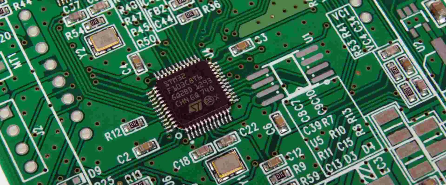
Where the plane under a trace is cut away, the distributed capacitance of the line falls and its inductance rises, so the impedance increases above the design value. The trace no longer sits in the field it was designed for.
The change also removes the confinement of the field. Without a plane to hold it, the field spreads into the surrounding material and into the space around the board, which increases coupling to neighbouring traces and raises the radiated emission at the same time.
Corners and Their Cost
A corner is a small discontinuity. It adds a little capacitance at the point where the trace turns, and a long route with many corners accumulates loss and mismatch, which is why a high speed route is kept as straight as the layout allows.
Corners are not the reason a route is length matched; matching exists to equalise delay between the members of a differential pair or between parallel buses. What the designer should avoid is an unnecessary turn, an unnecessary layer change and an unnecessarily long route.
Vias as Discontinuities
Every via adds inductance and capacitance to the path. The barrel has inductance, the pad has capacitance, and the unused portion of the barrel below the last layer it connects to acts as a stub that resonates at a frequency the signal may well contain.
That is why high speed designs use back drilling or blind and buried vias. Removing the stub restores the impedance through the transition and removes the resonance, and the effect is measurable as a cleaner eye diagram at the receiver.
Layer Changes and Return Paths
A layer change is not only a via problem. The return current has to move from one plane to another at the same point, and if no stitching via is provided beside the signal via, the return current must find another route, which lengthens the loop.
Placing a ground via next to every signal via that changes reference plane is one of the cheapest rules in high speed design. It costs a small amount of board area and removes a discontinuity that no amount of termination can correct.
Length Matching and Delay
Two traces of the same length on different layers do not have the same delay, because the dielectric and the geometry differ. Length matching therefore has to account for the propagation velocity of each layer, not just the geometric length.
Serpentine routing is used to add length, and it has limits. If the meander is tight the parallel sections couple with each other, which changes the impedance locally and can undo the matching it was meant to achieve.
Measurement and Verification
Impedance is verified with a coupon on the panel, measured with a time domain reflectometer. The coupon carries the same trace geometry as the design, and the fabricator reports the value so that the design assumption can be checked against the hardware.
On the board, a well matched route shows a clean eye diagram with little overshoot. Where the eye is closed, the cause is usually a plane split, a stub or a connector, and a measurement is a faster route to the answer than a change of termination value.
Rules That Are Cheap to Follow
Keep the reference plane solid under every high speed route, do not cross a split in the plane, place a ground via beside every layer change, keep stubs short and match lengths using the delay of the layer rather than its geometry.
The design rules that describe the trace geometry are usually documented as microstrip and stripline calculations, and the via rules that follow from them are just as important as the trace width itself.
When Matching Cannot Fix the Problem
A termination cannot repair a split plane, a connector with a large discontinuity or a route that is far too long. Those are layout problems, and they have to be solved in the layout, however accurate the impedance calculation is.
Matching is best understood as the last step of a chain that begins with the stackup and the floor plan. When the trace width and the reference plane have been chosen correctly, the termination value is a small calculation rather than a rescue attempt.
Single Ended and Differential Routes
A single ended trace is referenced to the plane and returns through it, so its impedance is defined against a ground that may be some distance away in the stack. A differential pair couples two traces to each other as well as to the plane, and its impedance depends on the spacing between them.
That coupling is why the spacing of a differential pair must be held constant. Where the two traces separate to pass a via or a component, the differential impedance rises, and the reflection that results is small but cumulative over a long route.
Where the Rules Are Relaxed
Impedance control costs money and board area, so it is applied where it changes the result. A slow control line, a status output or a signal that is shorter than a fraction of the rise time can be routed without any of these precautions.
The dividing line is the electrical length. When the round trip time along the trace is short compared with the rise time of the driver, the reflection returns before the receiver has finished switching and the effect is absorbed.
FAQ
Do all traces need impedance control? No. A short, slow net behaves well without it. Control is applied to high speed signals, clocks, interfaces and any line whose rise time is short compared with its length.
Why does removing the reference plane increase impedance? Because the capacitance between the trace and the plane falls while the inductance rises, and both changes push the impedance upward.
Are corners worse than vias? No. A via is a much larger discontinuity. A single corner is a minor effect, and it matters only when the route contains many of them.