Chip Wound Inductor Selection For DC-DC Converters
A chip wound inductor is a wire coil wound on a magnetic core and housed in a surface mount body, and it is the component that stores energy in most switching converters. Unlike a multilayer or a thin film part, the winding is a real coil, which gives it a higher inductance and a higher current capability for its size, at the cost of a larger body and a slightly higher profile.
Choosing one means balancing three parameters that move against each other: inductance, direct current resistance and rated current. This article looks at how the three interact with the converter and how to read the specifications without falling into the usual traps.
What The Construction Provides
The coil is wound on a ferrite or a metal powder core, and the ends are terminated so that the part can be placed and reflowed like any other surface mount component. The core material sets the saturation behaviour and the loss, while the winding sets the resistance and the current rating. A metal powder core saturates more softly than ferrite, which is often preferred in a converter because the inductance falls gradually rather than collapsing.
Because the winding is a physical coil, the part has an inter winding capacitance and therefore a self resonant frequency. Above that frequency the inductor behaves as a capacitor, so the part must be operated well below it. A larger inductance is achieved with more turns, which raises the capacitance and lowers the resonant frequency, so the two parameters cannot be improved together.
The switching frequency is the other variable that interacts with the choice. Raising the frequency allows a smaller inductance for the same ripple, which shrinks the body, but it also raises the core loss and the switching loss in the converter. The inductor and the frequency therefore have to be chosen together rather than one after the other.

Inductance And Ripple
The inductance sets the ripple current for a given switching frequency and duty cycle. A higher inductance produces a smaller ripple, which reduces the output voltage ripple and the root mean square current in the output capacitor. A lower inductance produces a larger ripple, which increases the loss in the capacitor and in the winding but improves the transient response because the current can change more quickly.
The usual starting point is to choose the inductance so that the ripple current is between about twenty and forty percent of the maximum load current. Below that range the converter is larger and slower than it needs to be, and above it the losses and the output ripple rise quickly. The value is a design decision rather than a datasheet parameter, and it should be confirmed by measuring the ripple on the actual board.
DC Resistance And Efficiency
The DC resistance of the winding produces a conduction loss equal to the resistance multiplied by the square of the current, so it has a direct effect on efficiency. It also affects the load regulation, because the voltage drop across the inductor appears as a droop at the output as the load rises, and in a current mode converter it shifts the current at which the loop regulates.
The resistance is not constant, because the copper heats up and its resistivity rises with temperature. A part specified at 0.048 ohms at room temperature is closer to 0.06 ohms at a hundred degrees Celsius, and the loss at the higher figure should be used in the efficiency calculation. The resistance also rises with frequency because of the skin effect, so the value quoted at direct current is a lower bound rather than the operating value.
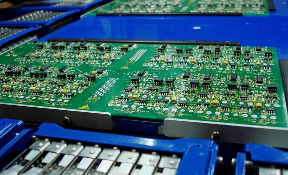
<img src="https://www.gopcba.com/wp-content/uploads/2026/08/led-pcb.webp" alt="Ripple current measured across an inductor in a DC-DC converter” />
Rated Current, Saturation And Temperature
Two current ratings appear on the datasheet and they are not the same thing. The rated current is the direct current that produces a specified temperature rise, usually forty degrees Celsius, in a defined mounting condition. The saturation current is the current at which the inductance has fallen by a stated percentage, commonly ten or thirty, because the core is saturating.
A converter has to satisfy both. If the peak current exceeds the saturation rating, the inductance falls and the ripple rises, which increases the peak current further and can run away. If the root mean square current exceeds the rated current, the part overheats. The peak of the ripple waveform, not the average load current, is what must be compared with the saturation rating, and the temperature rise must be evaluated at the ambient inside the enclosure rather than on an open bench. The behaviour of a part that loses inductance under load is closely related to the effects described for components under thermal stress during assembly.
Package Size Versus Performance
For a given inductance, a larger body allows a thicker wire and a larger core, so the DC resistance falls and the rated current rises. The table of a typical family shows this clearly: at one microhenry the smallest body has a resistance of about 0.048 ohms and a rated current of about two amps, a mid size body reaches 0.013 ohms and 5.4 amps, and the largest bodies go below 0.01 ohms with rated currents approaching eight amps.
The trade is the board area and the height, and in a compact product the height is often the binding constraint. The selection therefore starts from the mechanical envelope, then moves to the current requirement, and only then to the inductance that fits the remaining space. A part that meets the electrical requirement but does not fit the enclosure is not a candidate, and the iteration is faster if that order is respected.
Checking The Choice On The Bench
The final check is a measurement rather than a calculation. The ripple current should be measured with a current probe or inferred from the voltage across the inductor, and the temperature of the part should be measured after it has reached thermal equilibrium at full load in the enclosure. A part that is comfortable on an open bench can be well above its rated temperature once the lid is fitted.
The efficiency should be measured across the load range rather than at a single point, because the loss changes with the operating mode. A converter that is efficient at full load may be inefficient at light load if the inductance is small and the ripple is large. Where the result is marginal, the layout is usually part of the problem, and the guidance for routing a switching supply and for sizing the copper around the inductor is worth reviewing before the part is changed.
FAQ
Is a lower DC resistance always better? It reduces conduction loss, but it usually comes with a larger body. The right value is the one that meets the efficiency target within the mechanical envelope.
Which current rating should be compared with the load current? Neither directly. The peak of the ripple waveform is compared with the saturation current, and the root mean square current is compared with the rated current for temperature rise.
Why does the inductance matter less than expected at high load? Because a core that is approaching saturation loses inductance as the current rises, so the ripple grows and the peak current grows with it. That is why the saturation rating is checked at the peak, not at the average.