



SMT Component Shift: Causes and Fixes
A component that has moved from the position where the machine placed it is one of the most common assembly defects, and one of the most frequently misdiagnosed. The placement machine is blamed first because it is the visible actor, but a machine that is accurate to tens of microns is rarely the cause. Component shift is usually the result of a physical force acting on the part while the solder is molten, or of a process condition that lets the part move before the solder solidifies.
Nozzle Pressure and Pick-Up
The first place to look is the pick-up nozzle. If the vacuum pressure is too low, or the nozzle tip is worn or partially blocked, the component is not held firmly during the move from the feeder to the board. It may be released slightly off centre, or it may rotate slightly as the vacuum decays. The placement machine reports a successful placement because the part was delivered to the programmed coordinates, but the part is no longer aligned with the pads.
Nozzle condition matters as much as pressure. A worn tip leaks, a tip contaminated with flux or dust loses grip, and a nozzle that is the wrong size for the component allows it to sit off centre. Nozzle inspection and pressure verification should be part of routine maintenance rather than a reaction to a defect.
<img src="https://www.gopcba.com/wp-content/uploads/2025/08/4-1.png" alt="SMT component shift visible after reflow on a PCB” />
Solder Paste: Flux Content and Tack
The paste holds the component in place between placement and reflow, and it also generates the forces that act on the part while molten. Flux content that is too high produces a large volume of liquid that flows during the reflow cycle and can carry the component with it. The flow is not uniform across the board, so the effect is often a directional shift on one part of the panel and nothing at all elsewhere.
Tack is the other half of the story. Paste with insufficient tack does not grip the component, so the part can drift during handling, board transfer or vibration before it reaches the oven. Paste that has exceeded its shelf life or its working life behaves in exactly this way, because the flux chemistry degrades and the tack falls. The relationship between paste rheology and printing behaviour is described further in this article on solder mask ink thixotropy, since both materials are deposited through apertures and both depend on controlled flow.
Paste volume is the third variable. Too little paste leaves the component resting on the mask rather than on solder, and it will move at the first opportunity. Too much paste allows the part to float during reflow and to slide along the surface tension gradient.
Placement Accuracy and Self-Alignment
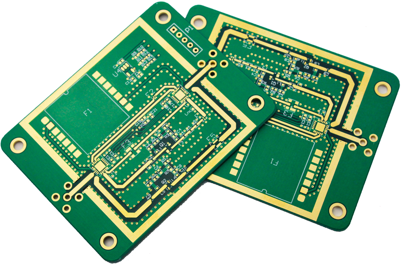
Self-alignment is the mechanism that corrects small placement errors. While the solder is molten, surface tension pulls the component toward the position where the wetted areas balance, which is normally the centre of the pads. That mechanism only works when the pads are equal in size, the paste volumes are equal and the part is within the pull-in range of the geometry.
It fails when the pads are asymmetric. A land pattern with one pad larger than the other, or with a different connected copper area, produces an unbalanced surface tension that pulls the component toward the larger pad. A defect that looks like a placement error can therefore originate in the pad geometry, and the rules that prevent it are set out in this discussion of PCB pad design standards. Self-alignment also fails when the paste volumes differ, which points back to the stencil and the printing process.
Reflow Profile and Thermal Imbalance
A component shifts when one end of it reaches the melting point of the solder before the other. The end that melts first wets its pad and pulls, while the other end is still held by solid paste and does not resist. The result is rotation or tombstoning, and the cause is a thermal imbalance between the two ends of the part.
Thermal imbalance can come from the profile itself, if the heating is not uniform across the panel, or from the board, if one pad is connected to a large copper area and the other is not. The second case is a design issue, and the correction is to balance the copper connected to the two pads so they heat at similar rates. Where the imbalance cannot be removed, a slower soak in the profile gives the assembly time to reach a more uniform temperature before the liquidus is crossed. The peak and the soak are set by the alloy, and the differences between alloy families are described in this article on lead-free and leaded solder.
Handling, Transport and Board Support
The period between placement and reflow is when a component with insufficient tack is most vulnerable. Vibration during conveyor transfer, a bump at the loader, or a board that flexes because it is not fully supported all produce movement. Support tooling that holds the board flat through the printer, the placer and the oven removes this class of defect entirely, and it is usually the cheapest correction available once the cause has been identified. A conveyor that accelerates abruptly at a transfer point is another common source, because the inertia of the board carries the components forward even though nothing has touched them.
Board support also affects the reflow itself. A board that is not flat during printing receives uneven paste deposits, and a board that sags in the oven heats unevenly. Both effects show up as shift or tombstoning on the parts affected, which is why the mechanical handling chain should be checked before the machine calibration is adjusted.
Working Through the Causes
When shift appears, the efficient order of investigation runs from the least invasive to the most. Check the paste first, including its age, its tack and the printed volume. Then check the nozzle pressure and condition, and the placement program for that specific component. Then examine the reflow profile with a thermocouple on the actual board, and only then consider the pad geometry and the copper balance. Most cases resolve in the first two steps, and the ones that do not are usually design issues that no process adjustment can fix. It is worth keeping a record of which cause was found each time, because the same cause tends to recur on the same product line.
FAQ
Why do components shift after reflow even though placement was accurate? Because the forces acting during reflow moved them. Unequal paste volumes, asymmetric pads, uneven thermal mass between the two terminations, or a large volume of flux flowing while the alloy is molten will all pull a component away from where it was placed.
How does paste cause component shift? Paste holds the part before reflow through its tack, and it generates the flow that acts during reflow. Insufficient tack lets the part drift during handling, while excessive flux content produces liquid that moves across the pad and carries the component with it.
Can component shift be prevented by design? Partly. Equal pad sizes, balanced copper connected to the two terminations and adequate clearance for self-alignment remove the main design contributions to shift. The rest is process control in printing, placement and reflow.


1 Comment
Tapping Test and Drop Test in Electronics Production - Kingda
[…] The tool is a rubber ball mounted on a wooden handle, and the test consists of striking the product with the ball while the product is powered and running. The ball should be chosen for size and weight, because both change the energy delivered and therefore the sensitivity of the test; the wrong ball makes the test either ineffective or destructive. Tapping is normally done three times at each location rather than once, so that an intermittent fault that does not appear on the first strike has a second and third chance. For products with a display, the operator watches for any glitch in the image while tapping, because a marginal joint often shows up as a momentary artefact rather than as a hard failure. The general defect mechanisms that this stimulus exposes are the same ones described in this article on SMT component shift causes. […]