
Pad Cratering and Microcracks in Ball Grid Array Assemblies
A solder joint can be perfectly formed and still fail, because the weakest link is often not the solder at all. When a ball grid array is loaded in bending, the copper pad and the resin beneath it can crack before the alloy yields. The result is pad cratering, a defect that hides under the package, passes electrical test, and appears months later as an intermittent open. Understanding how it forms is the first step to preventing it.
What Pad Cratering Looks Like
In a cross section, pad cratering appears as a crack that starts at the pad edge and travels down into the laminate, following the resin-rich region between glass bundles. The copper pad itself usually stays attached to the solder. Instead, a cone of laminate separates away with the pad, which is why the feature is described as a crater rather than a lifted pad.
The distinction matters for diagnosis. A lifted pad suggests a fabrication problem with pad adhesion or surface finish. A crater suggests a mechanical overload delivered after assembly, because the failure path runs through the bulk of the resin rather than along the copper-resin interface.
Why the Laminate Fails Before the Solder
Lead-free solders are stronger and stiffer than the tin-lead alloys they replaced. That sounds like an improvement, and for many failure modes it is, but it also means a given deflection produces a higher stress at the pad boundary. The load has to go somewhere, and the compliant layer beneath the pad becomes the weak point.
Resin-rich regions between glass bundles have lower fracture toughness than the surrounding composite. Cracks therefore seek those paths, which is why a crater often follows the weave direction rather than the shortest route to the surface. Inspection that only looks at the solder will conclude that the joint is fine while the real damage sits one layer below.
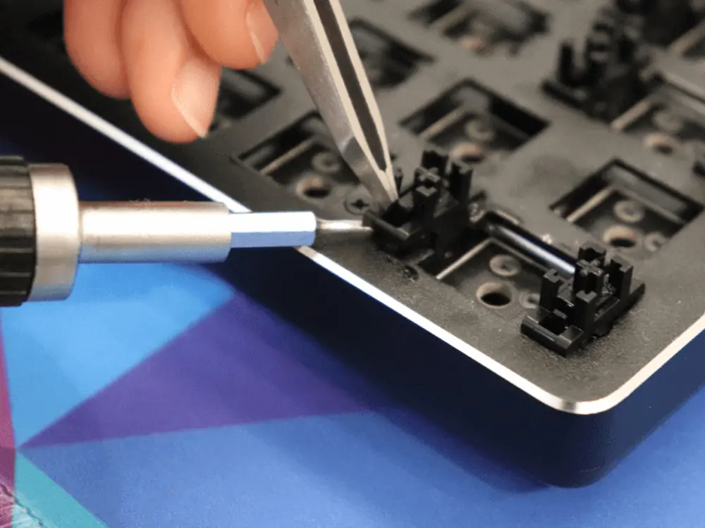
Where Cracks Start: Pad, Resin and Weave
The usual initiation site is the corner or edge of a pad where the copper terminates. That geometry concentrates stress, and it is also where the resin is often thinnest. Once a crack starts, it propagates along the interface between the copper foil and the resin, then turns down into the laminate when it meets a weaker path.
Weave structure influences the direction. Open-weave styles with large resin-rich windows give a crack an easy channel, while denser fabrics force it to change direction and slow it down. This is one reason that two laminates with almost identical datasheet properties can behave quite differently in a bend test, and why microcracks sometimes appear in one grade but never in another.
Ball Grid Array Packages Under Mechanical Stress
Most cratering is caused by bending, not by tension. Depaneling with a dull router, separating a panel by snapping it over a table edge, or supporting a board only at its perimeter during a functional test all introduce deflection. The outermost balls of a large package see the highest strain, which is why failures cluster at package corners.
Handling adds a second source. Pressing on a board to seat a connector, over-torquing a heatsink screw, or dropping a unit into a chassis all deliver load directly to the ball array. Because these events are rarely logged, the resulting damage is usually attributed to the assembly process rather than to the moment it actually occurred.
Detection: Cross Sections, Dye and Pry, and Acoustic Methods
Detecting cratering requires methods that reach under the package. A targeted cross section through the corner balls is the definitive approach, but it examines only the plane it cuts. Dye penetrant testing combined with mechanical removal of the package exposes the fracture surfaces across the whole array, which makes it the preferred survey method for a suspect lot.
Non-destructive options exist but are limited. X-ray sees solder voids and joint geometry well, but a laminate crack has almost no density contrast against intact resin, so it usually remains invisible. Acoustic methods can reveal separation at the pad-to-resin interface when the geometry allows access. In practice, screening with inspection and confirming with a physical section is the reliable sequence, and the trade-offs are summarised in this comparison of X-ray and optical inspection.
Depaneling, Handling and Board Flexure
Because the mechanism is mechanical, the most effective countermeasures are mechanical. Supporting the board directly beneath the package during depaneling, routing rather than snapping, and specifying a generous breakaway tab all reduce the strain delivered to the ball array. Tooling that follows the board contour instead of forcing it flat is worth the capital cost.
Handling discipline matters just as much. Fixtures that distribute clamping force, torque-controlled drivers on heatsink hardware, and clear instruction not to press on populated areas all address the everyday events that quietly do the damage. Reviews of component tolerance and reliability often surface these handling assumptions during design rather than after a failure.
Design Levers: Pad Size, Via-in-Pad and Laminate Choice
Pad geometry controls the stress concentration. A pad that is only slightly larger than the ball creates a sharp copper termination close to the joint, while a larger pad moves the termination further from the highest strain. Non-solder-mask-defined pads remove the mask step that can act as a crack initiator at the pad edge.
Via-in-pad without proper filling creates voids that behave as stress risers, so filled and plated over constructions are preferred under large packages. Laminate selection contributes as well, and the fracture behaviour discussed in this guide to laminate material properties explains why higher-toughness grades often justify their price in high-bend applications. Avoiding unnecessarily thin cores under a large package is another simple design decision with a measurable effect.
Reflow, Rework and Thermal Contribution
Thermal exposure does not cause cratering on its own, but it changes the material that later resists it. Repeated reflow cycles and rework degrade the resin around a pad, reducing the energy required to propagate a crack. A pad that has been reworked two or three times is measurably more vulnerable to a later mechanical event.
Rework also introduces a second problem: the mechanical force used to remove a package. Hot-gas removal with a twisting motion applies exactly the load that causes cratering, and the damage may not appear until the new package has been placed. Tracking rework count per board and limiting it by procedure keeps this contribution bounded.
Qualification Testing and Acceptance Limits
The standard way to quantify resistance is a bend or drop test on a daisy-chained coupon, with continuity monitored during the event. The deflection at first electrical failure, combined with a post-test dye and pry inspection, gives a repeatable measure of how much abuse a design can absorb before cratering begins.
Acceptance limits should be expressed as a minimum deflection or a minimum number of cycles at a defined strain, not as a pass or fail on a single sample. Because the failure is mechanical and statistical, a small sample can easily pass by luck. Retained coupons and a documented baseline turn a one-off test into a meaningful production control.
FAQ
How is pad cratering different from a lifted pad? A lifted pad separates along the copper-to-resin interface and usually points to a fabrication issue such as poor adhesion or contamination. Pad cratering fractures through the laminate itself, taking a cone of resin with the pad, and generally indicates mechanical overload delivered after assembly. The fracture path is the decisive evidence.
Can X-ray inspection find cratering? Rarely. A crack in resin has very little density contrast against the surrounding laminate, so it does not produce the clear image that a solder void does. X-ray remains valuable for confirming that joints are well formed, but cratering is normally confirmed by a cross section or by dye and pry testing.
Does reballing make the problem worse? It can, because reballing requires heating and mechanical handling of a package that is already attached to a board. The thermal cycles reduce the toughness of the surrounding resin and the removal force adds mechanical load. Where reballing is necessary, documenting the cumulative rework count and re-testing a sample afterwards is prudent.