Panelisation: PCB Panel Design and Material Utilisation
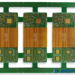
A production panel exists to make handling and processing efficient, but every panel carries material that becomes waste. The way the boards are arranged on the panel decides both the material cost and the process quality, and it is usually settled late.
Why Panelise at All
Very small boards cannot be printed, placed and reflowed individually at a sensible rate. The panel gives the machine a stable, standard size and it locates every board in the same place for every step.
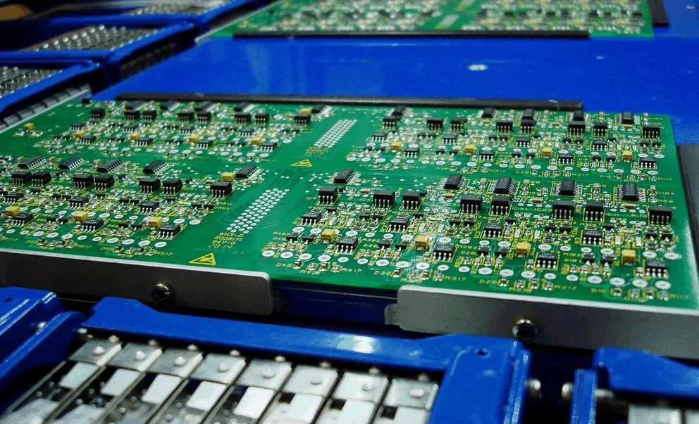
The panel also carries the tooling features the process needs: fiducials, tooling holes, a test coupon and the rails the conveyor grips. Those features consume area, so the usable area is always smaller than the panel area.
Material Utilisation
Utilisation is the board area divided by the panel area. It decides the material cost directly, and a layout that raises it by a few percent is worth the effort on a high volume product.
The ways to raise it are to choose a panel size that divides well into the board outline, to place the boards as closely as the routing or scoring method allows, and to use the margin for the tooling rather than leaving it empty.
Space Between Boards
The gap between adjacent boards is set by the separation method. A scored board needs room for the tool on both faces; a routed board needs the cutter diameter plus material for the tabs.
The gap is also a process limit. Below a certain width the router cannot be programmed accurately, and the resulting edge quality falls. Our breakaway tab notes describe how the tab geometry is set.

Rails and Tooling Features
The rails carry the panel through the printer, the placer and the oven. They must be wide enough to be gripped and flat enough not to distort the panel, and they must be free of components.
Fiducials should be on the rails or on the panel itself, in positions the machine can see, and they should be at least two per side so that rotation can be corrected as well as translation. Our outline tolerance notes cover the registration that the fiducials support.
Mixed Panels
Where several boards make up one product, they can be combined on one panel so that a single assembly run produces a complete set. This removes a matching step later and it increases the panel area that carries value.
The penalty is that every board on the panel then follows the same process, so the reflow profile and the stencil thickness are a compromise. Where one board carries a heavy connector and another carries fine pitch parts, the compromise is expensive.
Panel Size and Handling
The panel must fit the equipment that will process it, and it must be stiff enough not to sag in the oven. A panel that is too large flexes under its own weight at reflow temperature and the boards take a set.
The weight matters as well as the size. A dense panel with heavy components on both faces can exceed what the conveyor or the magazine can handle, and the limit should be checked before the panel is fixed. Our fabrication notes notes list the panel attributes that should be stated.
Verification
The panel design should be reviewed against the assembly equipment before the first order, because a change afterwards costs a stencil, a program and a fixture.
The first article then confirms what the review assumed: that the boards separate cleanly, that the fiducials are readable, and that the rails survive the full thermal cycle. Our quality notes describe how the result is recorded.
Additional Considerations for This Build
Practical attention to panelisation pays for itself here, because it decides whether the finished board behaves as the drawing intended. Where the requirement is not stated on the fabrication drawing or in the assembly notes, the shop has to assume a default, and that default is rarely the value the design was simulated with. Stating panelisation explicitly, together with the tolerance that applies, removes the assumption and keeps the result predictable from batch to batch.
Process Control and Verification
On a design of this kind, separation is the item that decides how the rest of the board is arranged. A short note on the drawing about handling, storage or packaging is often worth more than an extra decimal place on a tolerance. Where a value sits close to a process limit, the drawing should say so, since the shop can then open the process window rather than working to a nominal figure that carries no tolerance.
A stack-up that is drawn rather than described removes most of the ambiguity from a quotation, and it lets the fabricator price the board against the dielectric and copper weights that will actually be used. Where the requirement is not written down, the shop supplies its own default, and the default is chosen for the process rather than for the design.
The measurements that matter are the repeatable ones: conductor width and spacing, annular ring, finished hole size, plating thickness and surface finish are all verifiable on a coupon that travels with the panel. Running a first article through the same checks as the production panel confirms that the two agree, and that comparison is the cheapest form of process control available at prototype stage.
Keeping a sample from the panel turns a dispute into a measurement, because the same coupon can be re-examined by both parties without rebuilding the batch.
Process Control and Verification
On a design of this kind, separation is the item that decides how the rest of the board is arranged. A short note on the drawing about handling, storage or packaging is often worth more than an extra decimal place on a tolerance. Where a value sits close to a process limit, the drawing should say so, since the shop can then open the process window rather than working to a nominal figure that carries no tolerance.
A stack-up that is drawn rather than described removes most of the ambiguity from a quotation, and it lets the fabricator price the board against the dielectric and copper weights that will actually be used.
Process Control and Verification
On a design of this kind, separation is the item that decides how the rest of the board is arranged. A short note on the drawing about handling, storage or packaging is often worth more than an extra decimal place on a tolerance. Where a value sits close to a process limit, the drawing should say so, since the shop can then open the process window rather than working to a nominal figure that carries no tolerance.
A first article check confirms that the process and the drawing agree on the points listed above, and that the coupon data supports the values used in the design.
<img src="https://www.gopcba.com/wp-content/uploads/2026/06/AGV-Controller-System-PCBA.jpg" alt="Fiducials and tooling holes on a panel rail” />
Where a measurement falls outside the expected window, the sample is retained so that the cause can be established before the balance of the batch is released.
FAQ
Is a bigger panel always more efficient? No. Beyond the equipment limit the panel flexes and the handling becomes harder, and the gain in utilisation is lost to yield.
Should the rails be removed after assembly? They can be, and on a high volume product they usually are, but the removal step must not load the boards that are already assembled.
What does gopcb provide for panel design? We provide panel layout for material utilisation, gap and edge clearance rules for the chosen separation method, rail and fiducial and tooling hole definition, mixed panel studies, panel size and weight checks against the assembly equipment, and first article confirmation of separation and registration.