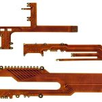
MEMS Microphone Interface Circuit Design
A MEMS microphone is a silicon device with a movable diaphragm and a fixed backplate, packaged with an application specific circuit and sealed with a lid that has a small hole. It is smaller and more consistent than an electret capsule, but it is also more sensitive to the printed circuit board it is mounted on, because the acoustic port is on the bottom of the package and opens directly onto the board.
How a MEMS Microphone Works
Sound enters through the port and moves the diaphragm, changing the capacitance between it and the backplate. The change is small, and the circuit inside the package converts it into an analogue signal or into a digital bitstream. The package also includes a charge pump in most designs, since a bias voltage is needed to sense the capacitance.
The package is a mechanical component as well as an electrical one. The lid and the substrate form a sealed cavity, and the only acoustic path is the port. Any leakage around the package, or a blockage of the port, changes the response. The port is usually on the bottom, so the board itself forms one wall of the acoustic chamber.
The internal charge pump produces switching noise at a frequency well above the audio band, and the package is designed to keep it inside. That is one reason the supply decoupling and the grounding around the device matter more than they would for a simple analogue part.
Analog and Digital Output Types
An analogue microphone outputs a signal at a level of a few millivolts per pascal, with a defined output impedance, and it requires an amplifier and an analogue to digital converter downstream. The signal is small, so the trace from the device to the amplifier is part of the noise budget.
A digital microphone outputs a one bit stream, usually in a pulse density format, on one or two data lines with a clock supplied by the host. The conversion happens inside the package, so the trace carries a robust digital signal instead of a microvolt analogue one, which is a considerable advantage in a dense product.
PDM interface devices can be configured in stereo by connecting the data lines in a defined way, with one device responding to one edge of the clock and the other to the opposite edge. The configuration is set by the state of a select pin, and getting it wrong produces two channels that are identical or a channel that is silent.

Signal to Noise and Acoustic Overload
signal to noise ratio is quoted in decibels relative to the maximum acoustic input the device can handle, and it is the parameter that decides how quiet a sound can be resolved. A device with a high ratio can be used further from the source or with more gain in the digital domain before the noise floor becomes audible.
The acoustic overload point is the level at which the device distorts by a defined amount, usually ten percent. A device used close to a loud source, such as a speaker or a machine, can be overloaded even though the signal chain is well designed. The two parameters together define the useful dynamic range, and both have to suit the application.
Wind and mechanical vibration produce a large low frequency signal that can push the device into overload even when the wanted sound is quiet. A mechanical windscreen, or a high pass filter in the digital domain, is the usual mitigation. Filtering cannot help once the device itself has clipped, so the mechanical arrangement comes first.
Acoustic Port and Mechanical Design
The port is a small hole, and its dimensions form part of the acoustic path. The cavity between the port and the diaphragm, combined with the mass of the air in the hole, produces a Helmholtz resonance that shapes the low frequency response. The gasket that seals the port to the enclosure and the volume of the front cavity both affect it.
The seal is critical. Acoustic leakage around the port reduces the low frequency output and makes the response depend on the assembly, so the same product can sound different from unit to unit. A compressible gasket of a defined hardness and thickness, with a controlled compression, is the way to make the response repeatable.
Placement inside the product follows from the same reasoning. The microphone should not be placed where it picks up airflow from a fan, nor directly in front of a loudspeaker where it will pick up the product of its own output. A short duct to the outside of the enclosure is normal, and the duct should be smooth and free of steps that would create turbulence noise.

Supply Noise and Power Supply Rejection
power supply rejection is the ability of the device to ignore noise on its supply, and it falls as the frequency rises. Switching regulator ripple in the audio band is therefore passed into the output, and the effect is audible as a tone or a buzz when the microphone is used in a quiet environment.
The cure is to keep the microphone supply separate from the switching rails. A low noise linear regulator dedicated to the audio devices, followed by a local filter, gives the cleanest result. Where a linear regulator is not available, a series ferrite with a capacitor forms a filter that reduces the ripple reaching the device, at the cost of a small voltage drop.
The decoupling capacitor is part of that filter and must be placed at the device pin. A capacitor shared between several microphones, or placed at the far end of a trace, does not supply the local current that the device draws. A small ceramic capacitor close to the pin, together with a larger one nearby where the supply enters the audio area, is the usual arrangement.
Layout and Interface Routing
For a digital microphone, keep the clock and data traces short and route them together with a ground return. The clock is a fast square wave and radiates, so it should not be routed across the audio area or beside a sensitive analogue input. The traces are short by nature because the device has to be at the port, which helps.
For an analogue microphone, the output trace is the critical one. It carries a signal of a few millivolts, so it must be short, guarded from switching nodes and routed over a continuous ground plane. The partition between the audio area and the rest of the board should be explicit, and the rules for that arrangement are described in mixed signal board design.
The microphone ground connection deserves attention because it is also the acoustic reference. A ground that carries switching current produces a voltage that appears as noise in the output, and a ground that is shared with the charge pump return of another device is worse. The general tolerance and reliability considerations that apply to the mechanical parts of the assembly are described in component tolerance and reliability.
Verification and Common Faults
Verify the device with an acoustic reference, measuring the output level for a known sound pressure and comparing it with the specification. Measuring in a quiet room with a calibrated source, or at least a repeatable one, gives a result that can be compared between units and between designs.
Measure the noise floor with the acoustic source silent. A noise floor above the specification suggests supply noise or interference on the output trace, and the two can be separated by powering the board from a battery while the rest of the system runs. A noise floor that changes when the display backlight turns on points to a coupling path.
A device that is quiet in one assembly and not in another usually has an acoustic leakage problem rather than an electrical one. Checking the gasket compression and the flatness of the surfaces around the port identifies it, and the release checks that make these items testable in production are described in PCB design release checklist.
FAQ
Can I share one decoupling capacitor between two microphones? Only if the trace to each is very short and the devices draw little current. A capacitor at each device pin is the safer arrangement.
Why is my microphone output weak at low frequencies? Acoustic leakage around the port or an oversized front cavity reduces the low frequency response. Check the gasket seal first.
Does the microphone have to be at the edge of the board? It has to be where the acoustic port can reach the outside air without a long or obstructed path. The electrical layout then follows from that mechanical constraint.