Selective Soldering for Mixed Technology Assemblies
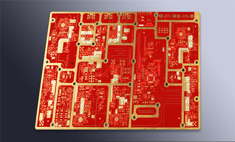
Most modern boards are a mixture. A densely packed surface mount area sits on one side, and a handful of connectors, transformers or power devices are still pushed through holes on the other. Sending that board across a wave solder machine would reflow the SMT side and damage parts that cannot survive immersion. Selective soldering solves the problem by delivering a small, controlled wave of molten alloy to one joint at a time.
Why Selective Soldering Exists
The alternative to selective soldering is hand soldering, and hand work brings variability that is difficult to control. Two operators produce different fillets on the same joint, and neither can reproduce a profile precisely. Selective soldering replaces that variability with a programmed machine that repeats the same motion and the same thermal exposure on every board.
The economics are also favourable once volume is sufficient. A machine amortised over thousands of boards costs less per joint than manual labour, and it produces a consistent record. For products with a small number of through-hole joints and a large SMT population, selective soldering is often the only practical method that meets both quality and cost targets.
How a Selective Soldering Machine Works
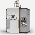
A pump inside a solder pot pushes alloy up through a nozzle to form a small standing wave. The board is positioned above the nozzle by a motion system, and the nozzle contacts only the area to be soldered. Because the wave is small, only local heat is applied and the rest of the assembly stays cool enough that previously reflowed joints are unaffected.
Multi-nozzle and multi-pot configurations allow several joints to be soldered simultaneously, or different alloys to be used on the same board. Modern machines also incorporate a vision system to locate fiducials and correct for board placement error, which matters because the margin between the wave and a neighbouring SMT part can be a millimetre or less.
Flux Application Options
Flux is normally applied before heating, and the method determines how much residue is left behind. Spray fluxing gives fine control and low residue, but overspray can contaminate adjacent areas. Drop fluxing delivers a measured droplet to each site and is very repeatable, while foam fluxing is faster and less precise and is rarely used for fine selective work.
Flux chemistry matters as much as the application method. A no-clean flux leaves residue that must be electrically safe, while a water-soluble flux requires a subsequent cleaning step that may be difficult on a mixed assembly. Because the flux must activate at the joint without leaving a harmful residue elsewhere, flux selection interacts with both the cleaning strategy and the product’s environmental requirements.
Nozzle Types and Solder Wave Geometry
The nozzle defines the shape of the wave and therefore the size of the joint it can produce. A round nozzle is a general-purpose choice for individual pins, while a slotted or rectangular nozzle suits a row of pins such as a connector footprint. A wide nozzle solders more joints in one pass but demands more careful alignment to avoid touching adjacent features.
Wave height is a critical setting. Too low and the joint does not fill the barrel properly; too high and solder climbs the pin and can bridge to a neighbouring contact. The correct height is established during process development and then verified by inspecting the barrel fill and the fillet shape on production parts rather than by trusting the machine display alone.
Thermal Profiling and Preheating
Selective soldering is a two-stage thermal process. Preheating brings the board and the joint to a temperature below the alloy melting point, and the nozzle then supplies the final heat required to form the joint. Without adequate preheat the nozzle dwell time must be long, which risks damage to the laminate and to nearby components.
Profiling uses thermocouples attached to representative joints, including the most thermally demanding ones such as a connection to an internal ground plane. A large thermal mass absorbs heat quickly and needs a longer dwell, while a small isolated pad can be overheated in the same pass. Programming per-joint parameters rather than a single global setting is usually necessary on real boards. Reviewing the overall sequence of operations in this guide to PCB production flow helps place profiling in the wider build.
Handling Mixed Technology Boards
Mixed assemblies impose geometric constraints. The nozzle must reach the through-hole joint without contacting the SMT components already placed on the same side, and the board carrier must hold the assembly without stressing reflowed joints. Tooling designed for the specific product is almost always required.
Order of operations is a decision with consequences. Soldering through-hole parts before reflow exposes them to a full thermal cycle and turns them into potential moisture damage sites, while soldering after reflow protects them but constrains nozzle access. Most processes choose selective soldering after SMT reflow, with the layout designed to leave clearance around the connectors. The related reliability considerations are covered in this overview of solder defect signatures.

Common Defects and Their Causes
Incomplete barrel fill is the most frequent complaint, and it usually traces to insufficient preheat, a dirty nozzle or a dwell that ends before the solder has risen through the hole. Bridging between adjacent pins appears when the wave height is too high or the flux is inadequate, and it is particularly common on fine-pitch connectors with a slotted nozzle.
Solder balls and spatter come from flux that is too active, from excessive wave turbulence, or from moisture in the laminate flashing off at the nozzle. Peeling solder mask around the joint indicates excessive nozzle temperature or dwell, and it often precedes more serious laminate damage. Each defect points to a specific setting, which is why recording parameters alongside defects shortens every investigation.
Comparing Selective with Wave Soldering
Wave soldering sends the entire board across a broad wave and is fast and inexpensive per joint, but it demands that the whole assembly tolerate immersion, including any SMT already attached. It also applies thermal load to areas that may not need it. Where a board has many through-hole joints and no heat-sensitive SMT, wave soldering remains the more economical choice.
Selective soldering trades throughput for control. Only the joints that need solder are heated, so adjacent components and the laminate see far less stress. Where a board has a large SMT population and a small number of through-hole joints, or where different alloys are required on the same assembly, the selective approach is usually the only one that works. Judging which method suits a product is essentially a question of quality judgement applied to the assembly sequence rather than to the board alone.
Process Control and Verification
Routine control is built from a small number of measurements. Nozzle temperature, wave height and dwell time should be logged per shift, and the flux volume delivered should be checked against the specification. A dirty or partially blocked nozzle changes the wave shape long before an operator notices it visually, so cleaning intervals deserve a defined schedule.
Verification of the output should include periodic cross sections of production joints, because barrel fill cannot be judged from the surface. Visual inspection catches fillets, bridging and spatter, while a section confirms that the hole is filled to the required percentage. Combining both gives a process that is controlled rather than merely inspected.
FAQ
Can selective soldering replace hand soldering entirely? In most volume production it can, and it produces far more consistent joints. The exceptions are very small prototype quantities, repairs, and joints in locations the nozzle physically cannot reach. In those cases hand soldering remains necessary, with the caveat that it requires its own operator qualification and inspection criteria.
Does selective soldering damage nearby SMT components? It can if the dwell is excessive or the nozzle is placed too close, but the localised nature of the heat is exactly what makes the method attractive. Preheating the whole board gently and then applying short, targeted nozzle heat keeps the peak temperature at nearby SMT joints below their reflow threshold in most designs.
Why is barrel fill harder to achieve with selective soldering? Because the heat is applied to one side of the board and the hole must conduct it upward to melt solder through the full thickness. Thick boards and heavy ground planes absorb heat quickly, so the nozzle must dwell longer. Verification by cross section, not by visual inspection, is the only reliable way to confirm fill.