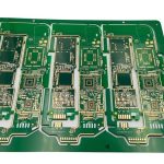
Hall Current Sensor Circuit Design
A Hall current sensor measures the magnetic field that a current produces and reports the current without inserting a shunt in the path. That isolation from the measured circuit is the reason it appears in motor drives, battery management and power supplies, and it is also the reason its accuracy behaves quite differently from a resistive shunt.
How the Measurement Works
The conductor passes through or around a magnetic core, and the field in the core is proportional to the current. A Hall element placed in the gap of that core produces a small voltage proportional to the field, and an amplifier turns that into a usable output.
The element is a thin semiconductor plate with a bias current through it. The magnetic field deflects the carriers to one side and produces a voltage across the other pair of terminals. The sensitivity is a few tens of millivolts per tesla for a bare element, which is why the core concentrates the field and the amplifier follows immediately.
Without a core, the field of a single conductor is small, and a coreless design has to rely on a very sensitive element or on a high current. That is why a coreless sensor is limited to high current applications and why the cored version dominates at moderate currents.
Open Loop and Closed Loop Cores
An open loop sensor measures the core field directly. It is simple, cheap and fast, and its accuracy is limited by the linearity of the core and the gain of the amplifier, typically a few percent of reading over the range.
A closed loop sensor adds a secondary winding and drives a current through it to cancel the flux in the core. The core then operates at zero flux, the linearity and the offset no longer depend on the core material, and the accuracy improves by an order of magnitude.
The price of the closed loop design is a drive amplifier, a compensation winding and more supply current. Where the measurement is used for control rather than protection, the extra accuracy usually justifies the cost and the board area.
magnetic core, Gap and Saturation
The core material determines the saturation level, the temperature behaviour and the loss. A ferrite core suits moderate frequencies, a laminated silicon steel core suits higher currents, and a nanocrystalline core gives the best performance per unit volume for a precision sensor.
The air gap is where the element sits, and its length sets the field for a given current. A longer gap gives a lower field and a wider range before saturation, while a shorter gap gives more sensitivity. The gap also affects the fringing field and therefore the linearity.
Saturation is the hard limit of the range. Above it the output stops following the current and the reading becomes meaningless, which matters when the sensor is used for overcurrent protection. Choosing a core that saturates well above the largest fault current keeps the protection meaningful.

offset drift and Its Sources
The offset is the output with no current, and its drift with temperature is the dominant error in most practical designs. It comes from the Hall element itself, from the mechanical stress in the package and from the amplifier that follows it.
Chopper stabilised amplifiers remove their own offset but not the offset of the element. A common technique is to spin the bias current of the element, reversing it and averaging the two readings, which cancels the element offset at the cost of a slower response.
Mechanical stress is the reason a Hall sensor should not be clamped with a screw that bends the package. A strain of a few hundred microstrain in the silicon shifts the offset noticeably, and a sensor mounted under a tightened screw shows a different zero after assembly than before.
Stray Fields and Shielding
An external magnetic field adds to the field of the measured current and appears as an error. The classic remedy is a toroidal core that guides the external field around the gap, which is why a closed ring core is far more immune than an open one.
Adjacent conductors are the most common source of a stray field. Two busbars running side by side couple a fraction of one current into the other sensor, and the error changes sign when the direction of the neighbouring current reverses. Keeping the cores apart and orienting them at right angles reduces the coupling.
Where a magnetic field cannot be avoided, a shield of high permeability material around the sensor diverts part of it. The material and the thickness follow the same reasoning as any ferrite component, and the selection criteria are set out in our guide to ferrite bead selection for EMI.
measurement range and Overcurrent
The measurement range is the span over which the specified accuracy holds. Beyond it the sensor may still produce a proportional output, but the error grows and the core approaches saturation, so the range must be stated with the accuracy that goes with it.
For a protection function the sensor has to represent a fault current of several times the nominal rating. A separate range or a second sensor with a wider span is often used, and the firmware switches between them when the current crosses a threshold.
The bandwidth matters for the same reason. A motor drive needs the sensor to follow the current ripple at the switching frequency, which means a bandwidth well above it. A sensor that is accurate at direct current but slow in bandwidth reports the average of the ripple rather than its peak.

isolation and Creepage Distance
The whole point of the sensor is that the measuring circuit does not touch the measured conductor, so the isolation is the safety feature. The barrier is formed by the thickness of the insulation and by the creepage distance along the surface of the package and the board.
The working voltage, the transient overvoltage and the pollution degree of the environment all determine the required distance. A sensor rated for reinforced isolation has an internal barrier that meets the standard, but the board layout around it still has to maintain the distance between the primary and secondary copper.
Slots and cutouts in the board are used to increase the effective creepage where the required distance is large. The layout of the barrier follows the same rules as any isolated interface, and the general principles for keeping the two sides separate are described in our guide to mixed signal board design.
Signal Conditioning and Output
The output stage turns the amplified element voltage into a form the system can read: a voltage proportional to the current, a current loop, or a digital value from an integrated sensor. The choice follows the distance to the controller and the noise environment.
A ratiometric output varies with the supply, so a system that reads it must use the same supply as its reference. An absolute output is more convenient but needs a stable supply inside the sensor, which is why many integrated sensors include their own regulator.
Filtering at the output has to respect the bandwidth requirement. A capacitor chosen for a quiet reading slows the response to a real current step, and a protection function that is late by a few tens of milliseconds may not protect anything. The filter is set from the fastest event that must be caught.
Verification and Common Faults
Verify the zero first. With the primary current removed, the output should sit at its specified quiescent value, and any deviation is the sum of the sensor offset and the amplifier offset. Measure it at two temperatures to separate a fixed offset from a drift.
Then verify the gain with a known current, using a traceable meter or a calibrated source. A gain error that grows with current points to core saturation or to amplifier compression, while a constant percentage error points to a gain setting.
A reading that changes when a nearby machine starts is a stray field problem rather than a sensor fault. Move the sensor, reorient it, or add a shield. The inspection and release practices that keep these assemblies consistent between units are collected in our PCB design release checklist.
FAQ
Why does my Hall current sensor read a current when none flows? That is the offset, and it drifts with temperature. Check the mounting stress on the package and measure the zero at two temperatures.
Is a closed loop sensor worth the extra cost? For control loops and precision measurement, yes. Its linearity and offset are far better because the core runs at zero flux.
Can I use a Hall sensor for overcurrent protection? Yes, if the core is chosen to saturate well above the fault current and the bandwidth is higher than the switching frequency of the load.